Honeywell
13
Off Off Off Off On 1
Off Off Off On Off 2
Off Off Off On On 3
Off Off On Off Off 4
Off Off On Off On 5
……
On On On On On 31
Note: Each group has 64 output channel addresses, 0 is 1-64; 1 is 65-128 etc. This
output group of output board and input board should be same in one chassis, otherwise
the switch function can’t work.
Push Buttons
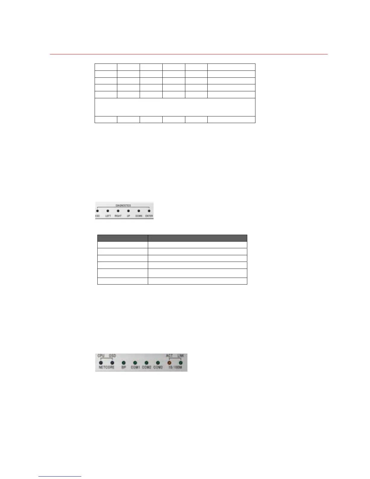
Push buttons on the front panel (see Figure 2-7 ) are used to select various diagnostic
parameters.
Figure 2-7 Six Push Buttons
If buttons are pressed while the chassis is powered up (or reset), then additional
functions are possible:
LED Indications
LEDs on the front panel are used to display working status of the chassis.
Figure 2-8 Diagnostics LED
Push Button Button Function
ESC Exit the operation
Left Select previous diagnostic parameter
Right Select next diagnostic parameter
Up Select previous diagnostic screen
Down Select next diagnostic screen
ENTER Select corresponding menu
 Loading...