VideoBloX MODULES
4
2 VideoBloX MODULES
VB CHASSISS CONNECTIONS
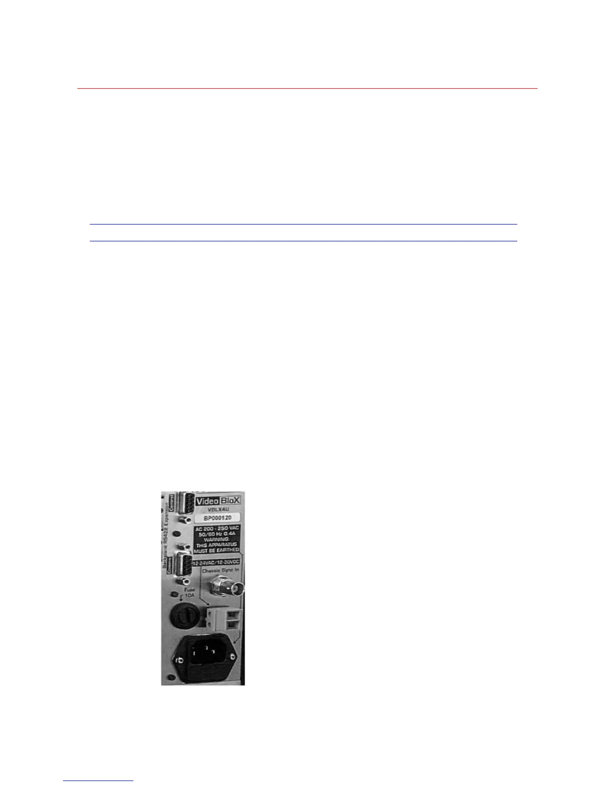
Figure 2-1 displays the rear view of the 4U chassis (HVB4U). Note that the connections
of the 8U (HVB8U) and 12U (HVB12U) chassis are identical.
Note: 2U Chassis (HVB2U) should be powered by 24 VAC derived from a low
capacitance-coupling transformer, such as a split bobbin transformer. Refer to Low
Voltage Input Connection
Main Input Power Connection
The main input power connector is a standard IEC power connector. This should be
connected to the main input power supply, which may be 50 or 60 Hz. Make sure that the
input voltage matches the voltage rating shown on the rear panel of the chassis. The
earth connection must also be mode. The main input connector incorporates a fuse
holder, which protects the main input power only. Note that the second fuse on the rear
panel of the chassis is for the low voltage input only.
Ideally, the main input power supply should have low noise levels, minimum voltage
fluctuation and be protected against over voltages such as those induced by lightning.
Figure 2-1 Rear View of VideoBloX Chassis’ Main Power
 Loading...