VideoBloX MODULES
8
8. Fasten the power supply module using the 2X fixing screws.
NETCPU & NETOSD MODULE
A VideoBloX system is controlled by a single master CPU module. For an expanded
system, with multiple chassis, it is possible to interconnect the chassis and have a single
CPU module control the entire system
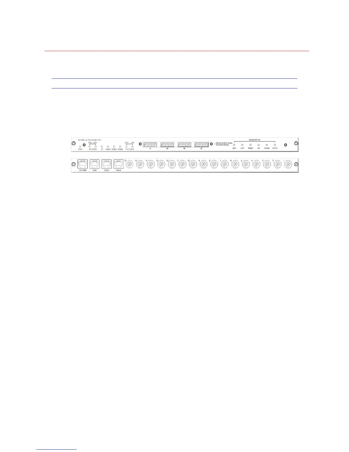
Figure 2-3 Front and Rear Views of CPU Module
All system configurations are carried out by means of a PC running Windows 95 / 98 /
98SE / 2000 / XP or NT, which connects to the CPU module. Once configuration is
complete, the PC may optionally be detached or used as a system activity logger. All
configuration information is stored in non-volatile memory and is retained during a power
loss for one month.
The NETCPU & NETOSD module monitors the operation of all modules installed into a
chassis or sub-chassis. The software/operating system is installed into this module.
Features of the NETCPU and NETOSD modules are described as follows:
• NETCPU functions and NETOSD functions integrated in one single board
• 66.7MHz processor core Motorola Coldfire, 32 bit RISC CPU
• 16MB flash memory to store system firmware
• uCLINUX Operating System
• Firmware can be upgraded via network
• Non-volatile RAM memory to store system variables, configurations and
downloaded system code extensions
• Power Supply monitor, automatically restart system operation in the event of
supply brownouts
• 10/100 base T Ethernet LAN connectivity
• Lithium backup batteries
• Front panel diagnostic indications
• Respective power supply for the NETCPU and NETOSD
• Four serial ports for communication and control
• DIP switch for COM channel settings
• 16 video signal outputs
• Six pushbuttons support flexible system information browse
 Loading...