Honeywell
143
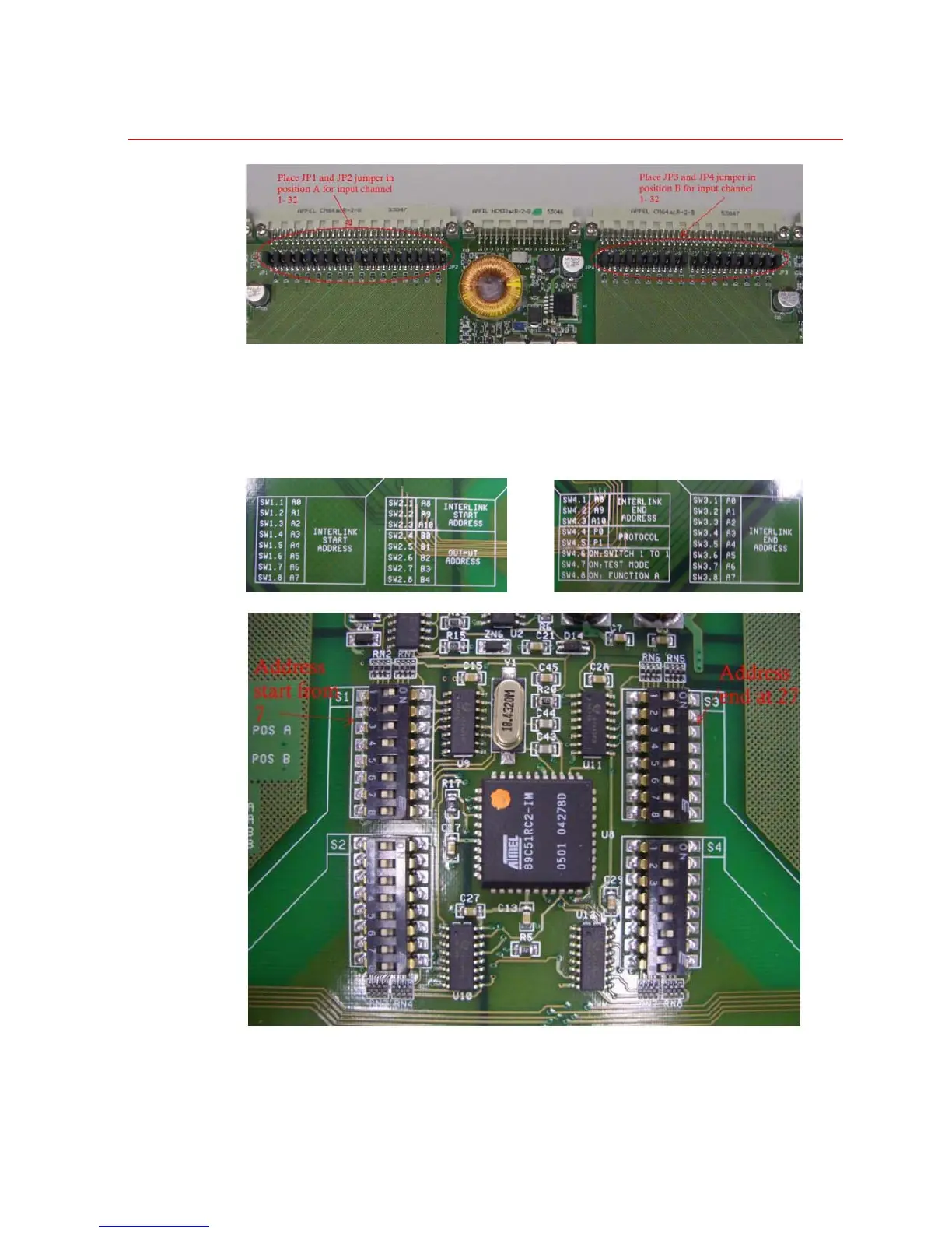
2. In the 1
ST
Slave chassis, two 1 x HVB16M64 input cards will be installed from
address 7 to address 27. Therefore, set 1 x HVB32LKI for channel 1
¡ª 32 and 1 x
HVB32LKI for channel 33
¡ª 64 address dip switch as below picture. Install those 2
HVB32LKI into Master chassis.
Figure 5-8 Inter-Link Start and End Address of 1
st
Slave Chassis
3. In the 2
nd
Slave chassis, another two 1 x HVB16M64 input cards will be installed from
address 28 to address 48. Therefore, set 1 x HVB32LKI for channel 1 -
32 and 1 x
 Loading...