Honeywell
37
Figure 2-53 Back Plane Video Channels Selection for interlink input module
DIP Switch Settings
Figure 2-54 DIP SW Settings for interlink input module
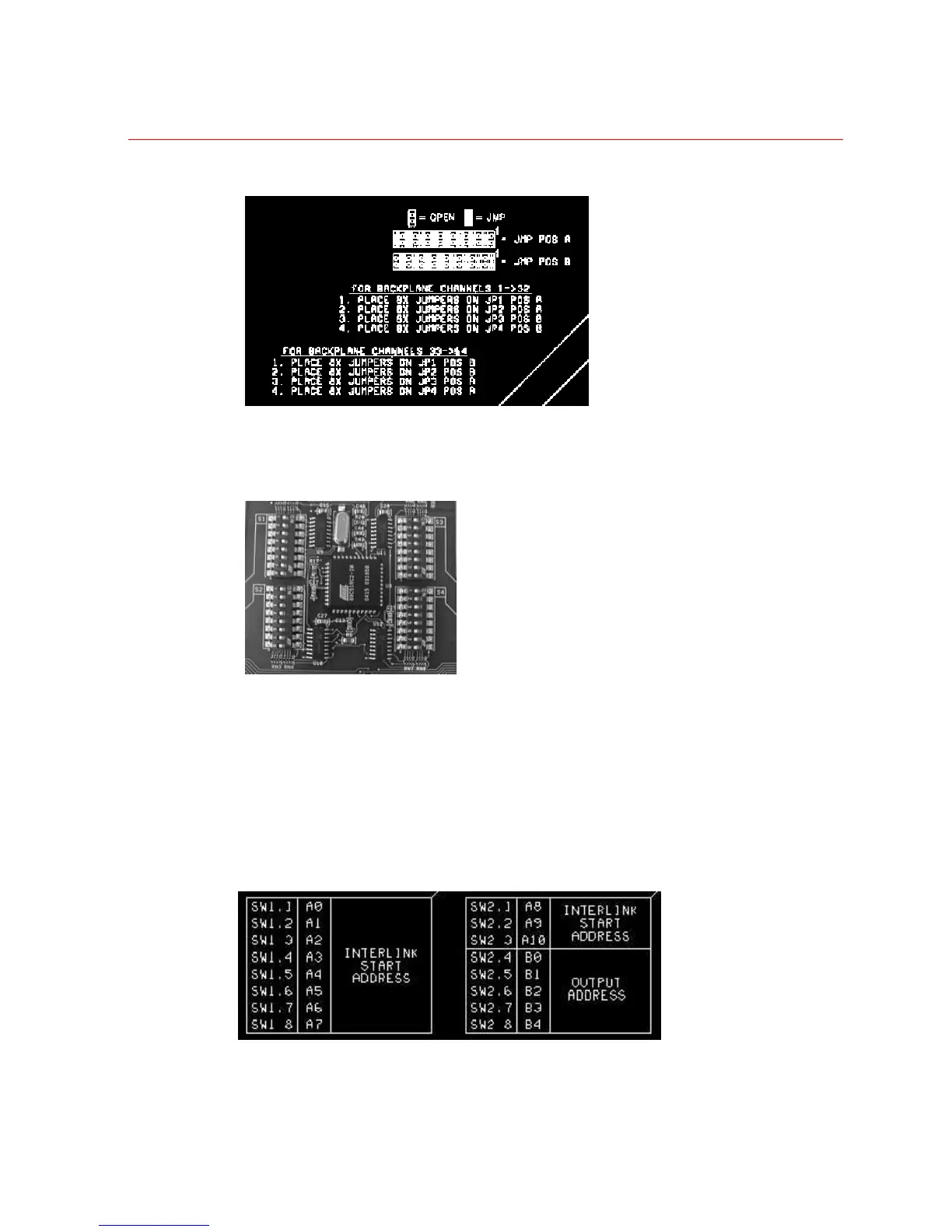
Set the Interlink Input DIP switches as follows:
• Set the “Start Address” SW1 (1-8) and SW2 (1-3) to match the address of the
first input card within the connected sub-chassis.
• Set S2 (4-8) to determine which group of the 64 output signals this module will
control. For monitors 1-32, SW2/4 – SW2/8 should be set to 00000; for monitors
33-64 SW2/4 – SW2/8 should be set to 00001.
Figure 2-55 SW1 and SW2 settings for interlink input module
 Loading...