VideoBloX MODULES
32
• Phantom powering option
• 20 dB pad to cater for a wide range of input signal levels.
• High pass and low pass filter options
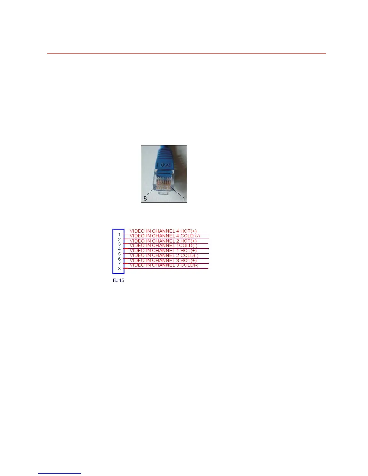
PIN OUT of RJ45 termination
Each RJ45 port can accommodate four audio inputs. The detailed pin out is as below.
Figure 2-44 Pin of RJ45
DIP Switch Settings
Perform the following steps to set the Audio Input Module DIP switches.
• S1 (1-8) sets the module address. This must be non-zero. A value of 1
addresses the card to accept audio inputs 1 to 16, etc.
• S2 (1) Turn on to associate the module with output channels 65 to 128.
• S2(2) Turn on to cause the module to work transparently as a slave to another
input module. This mode allows two cards to work synchronously for switching
stereo signals.
• S2(3) Turn on to cause the module to automatically switch its 16 audio inputs to
16 audio outputs when power up. In this mode, the address switch determines
which output group will be used.
• S2/4 Turn on to cause the module to enter test mode. In this mode, the module
rapidly cycles various inputs to outputs. This is useful for bench-top faultfinding
and should not normally be used in the field.
 Loading...