Honeywell
27
LED Indications
The LED on the front panel of the input card indicates the power status. Each time that a
serial message is received via the backplane port, the LED will flash briefly.
Fuse
The input module has a 4A fuse mounted on the board. This fuse should only blow in the
event of a fault on the board. In such an event the input module should be returned to a
Betatech distributor for repair.
Connections
The standard video input is connected by a BNC connector.
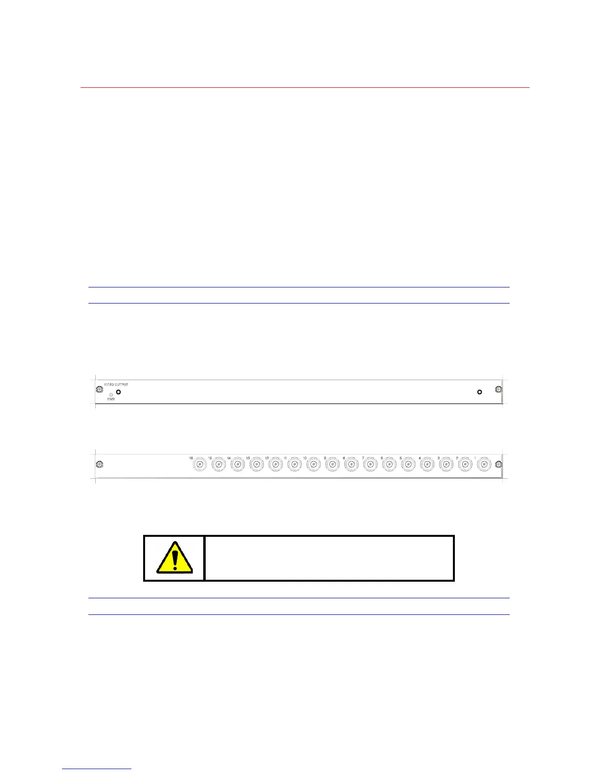
VIDEO OUTPUT MODULES
The video output module provides 16 video signals from the VideoBloX chassis. Each of
the outputs is associated with one of the 64 backplane channels.
Figure 2-32 16 Channel Video Output Modules - Front View
Figure 2-33 16 Channel Video Output – Rear View
The output module has limited protection against over-voltages, such as those induced
by a nearby lightning strike. It also has a range of jumpers which are populated to
determine which group of 16 video outputs the module receives from the backplane.
WARNING: The user should not modify the jumpers.
Output cards should be ordered for specific output channels.
TITLED VIDEO OUTPUT MODULE
The titled video output module output 16 titled video signals from the VideoBloX chassis.
Each of the outputs is linked to one of the 64 backplane channels.
 Loading...