Honeywell
7
Switch 3 is used to determine whether the chassis generates or receives system
synchronization signal.
Switch 4 is used to set the chassis to be the master or slave when multiple VideoBloX
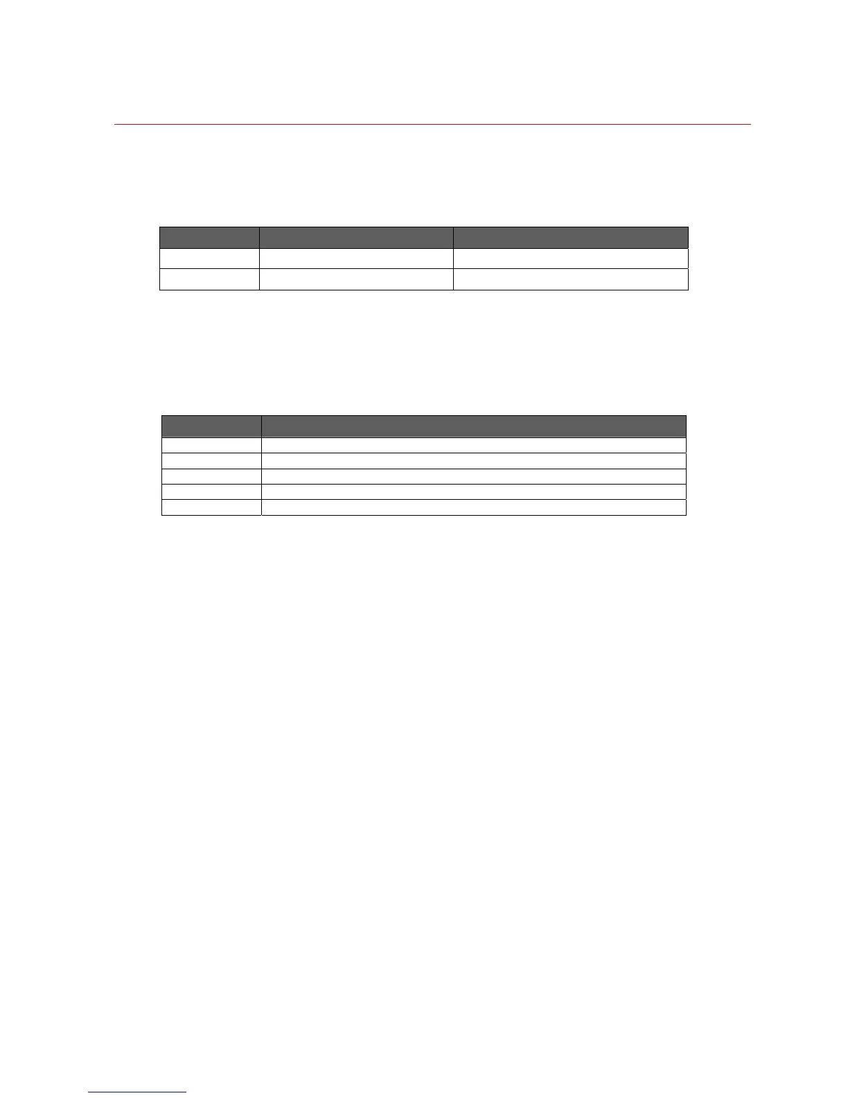
chassis are connected. Refer to the following table for detailed information.
Switch Position Off On
3
Chassis generates system sync
Chassis receives system sync signal
4 Chassis is a master Chassis is a slave
Reset Push Button
When this button is pressed, the chassis will be reset. Should the chassis be configured
as a master, then all slave chassis will also receive a reset signal.
Indications
LED Name Description
Tx Data Flashes when there is data present on the backplane transmit data line
Rx Data Flashes when there is data present on the backplane receive data line
RTS Flashes when the chassis is transmitting data
Video Sync On when sync input is present
Reset On when the reset signal on the backplane is active
Sync Phase Adjustment
This adjustment determines the sync phase with respect to the main waveform. When
sync is received via the rear panel "Chassis Sync In" BNC or via the "Control" connector,
this adjustment will have no effect.
Chassis Expansion Driver Board
This is an optional PCB which is plug into the power supply module. This board contains
the drivers and receivers which are necessary to interconnect master / slave chassis
together. This is required when one or more slave chassis are connected to a master
chassis. For a system which uses only one chassis, this optional board is not required.
Fitting Procedure:
1. Remove power from chassis
2. Remove 2 X fixing screws which secure power supply module to the front panel
3. Remove power supply module from chassis
4. Line up dual row connector on power supply board with expansion driver board.
5. Carefully press board into place.
6. Fasten board in place with 2 X M3 mounting screws.
7. Insert power supply module into chassis, carefully lining up with the chassis
connector. Press all the way in.
 Loading...