181
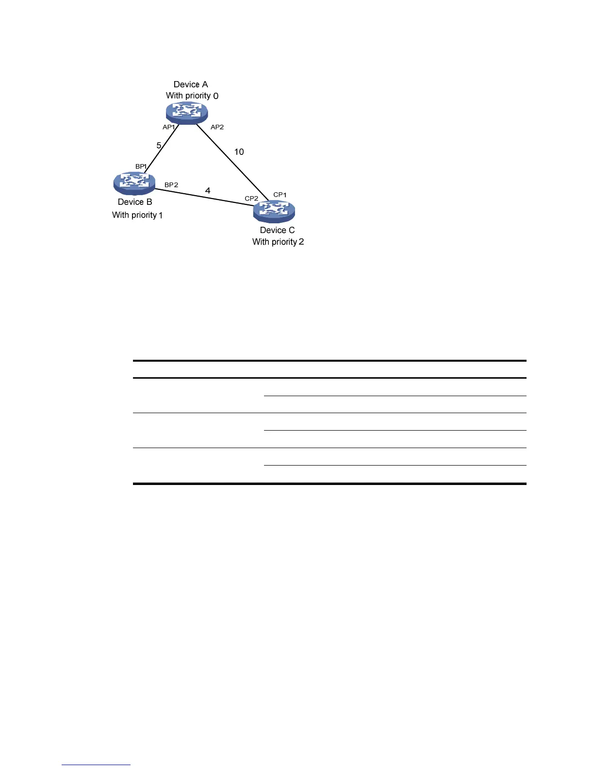
Figure 174 STP network
As shown in Figure 174, the priority values of Device A, Device B, and Device C are 0, 1, and 2, and the
path costs of links among the three devices are 5, 10, and 4, respectively.
1. Device state initialization.
In Table 55, each configura
tion BPDU contains the following fields: root bridge ID, root path cost,
designated bridge ID, and designated port ID.
Table 55 Initial state of each device
Device Port name BPDU of
ort
Device A
AP1 {0, 0, 0, AP1}
AP2 {0, 0, 0, AP2}
Device B
BP1 {1, 0, 1, BP1}
BP2 {1, 0, 1, BP2}
Device C
CP1 {2, 0, 2, CP1}
CP2 {2, 0, 2, CP2}
2. Configuration BPDUs comparison on each device.
In Table 56, each configura
tion BPDU contains the following fields: root bridge ID, root path cost,
designated bridge ID, and designated port ID.

 Loading...