303
DHCP relay agent configuration example
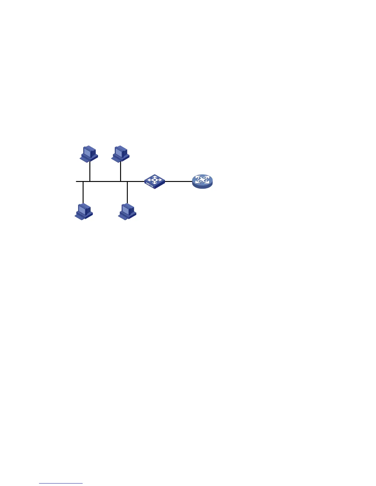
Network requirements
As shown in Figure 279, VLAN-interface 1 on the DHCP relay agent (Switch A) connects to the network
where DHCP clients reside.
The IP address of VLAN-interface 1 is 10.10.1.1/24 and the IP address of VLAN-interface 2 is 10.1.1.1/24.
VLAN-interface 2 is connected to the DHCP server whose IP address is 10.1.1.1/24.
The switch forwards DHCP messages between DHCP clients and the DHCP server.
Figure 279 Network diagram
Configuring Switch A
1. Enable DHCP:
a. From the navigation tree, select Network > DHCP to enter the default DHCP Relay page.
b. Select the Enable option next to DHCP Service, as shown in Figure 280.
c. Cli
ck Apply.
DHCP server
Switch A
DHCP relay agent
DHCP client DHCP client
DHCP clientDHCP client
Vlan-int2
10.1.1.2/24
Vlan-int1
10.10.1.1/24

 Loading...