43
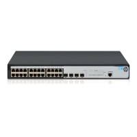
Figure 29 Device summary (a member device)
Stack configuration example
Network requirements
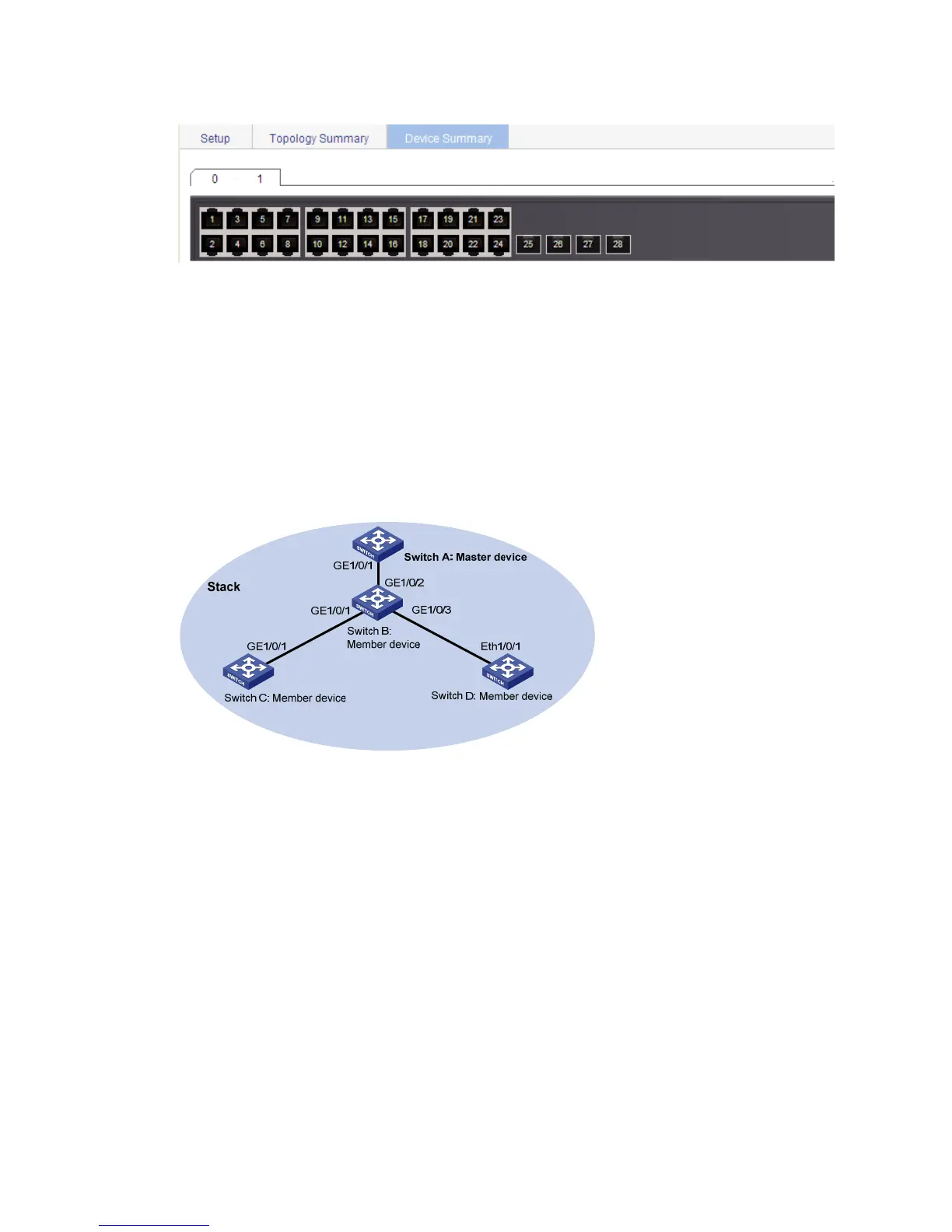
As shown in Figure 30, Switch A, Switch B, Switch C, and Switch D are connected to one another.
Create a stack, where Switch A is the master device, and Switch B, Switch C, and Switch D are member
devices. An administrator can log in to Switch B, Switch C, and Switch D through Switch A to perform
remote configurations.
Figure 30 Network diagram
Configuration procedure
1. Configure global parameters for the stack on Switch A:
a. Select Stack from the navigation tree of Switch A, and then perform the subsequent steps on the
Setup tab, as shown in Figure 31.
b. Typ
e 192.168.1.1 in the field of Private Net IP.
c. Type 255.255.255.0 in the field of Mask.
d. Select Enable from the Build Stack list.
e. Click Apply.

 Loading...