Partner Port ID of the peer port.
Partner Port State
States of the peer port:
• A—LACP is enabled.
• B—LACP short timeout. If B does not appear, it indicates LACP long timeout.
• C—The sending system considers the link is aggregatable.
• D—The sending system considers the link is synchronized.
• E—The sending system considers the incoming frames are collected.
• F—The sending system considers the outgoing frames are distributed.
• G—The sending system receives frames in the default state.
• H—The sending system receives frames in the expired state.
Oper Key Operational key of the local port.
Table 68 Field description
Field Descri
Unit Number of the remote system.
Port Name of the remote port.
Partner ID LACP priority and MAC address of the remote system.
Partner Port Priority LACP priority of the remote port.
Partner Oper Key Operational key of the remote port.
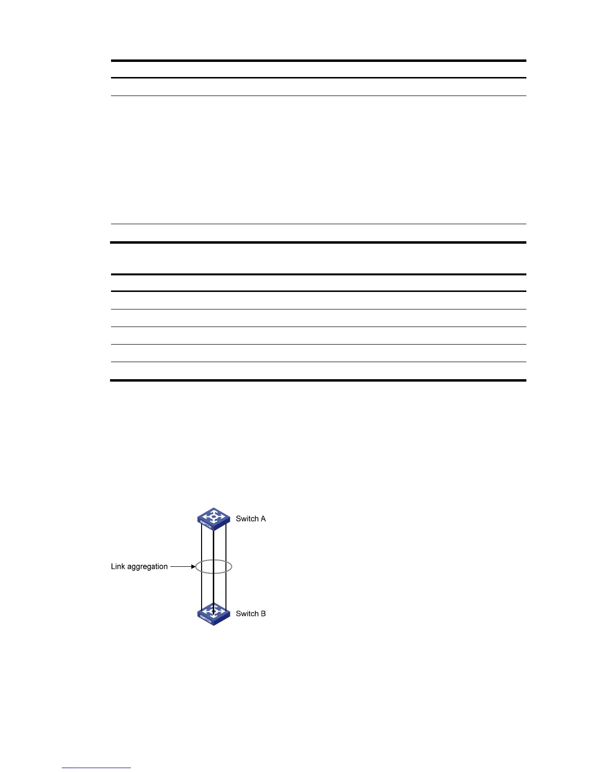
Link aggregation and LACP configuration example
Network requirements
As shown in Figure 192, create a link aggregation group on Switch A and Switch B to load-share
incoming and outgoing traffic across the member ports.
Figure 192 Network diagram
Method 1: Create static link aggregation group 1
1. From the navigation tree, select Network > Link Aggregation.
2. Click Create.
3. Configure static link aggregation group 1:
GE1/0/1
GE1/0/2
GE1/0/3
GE1/0/1
GE1/0/2
GE1/0/3

 Loading...