441
Port isolation configuration example
Network requirements
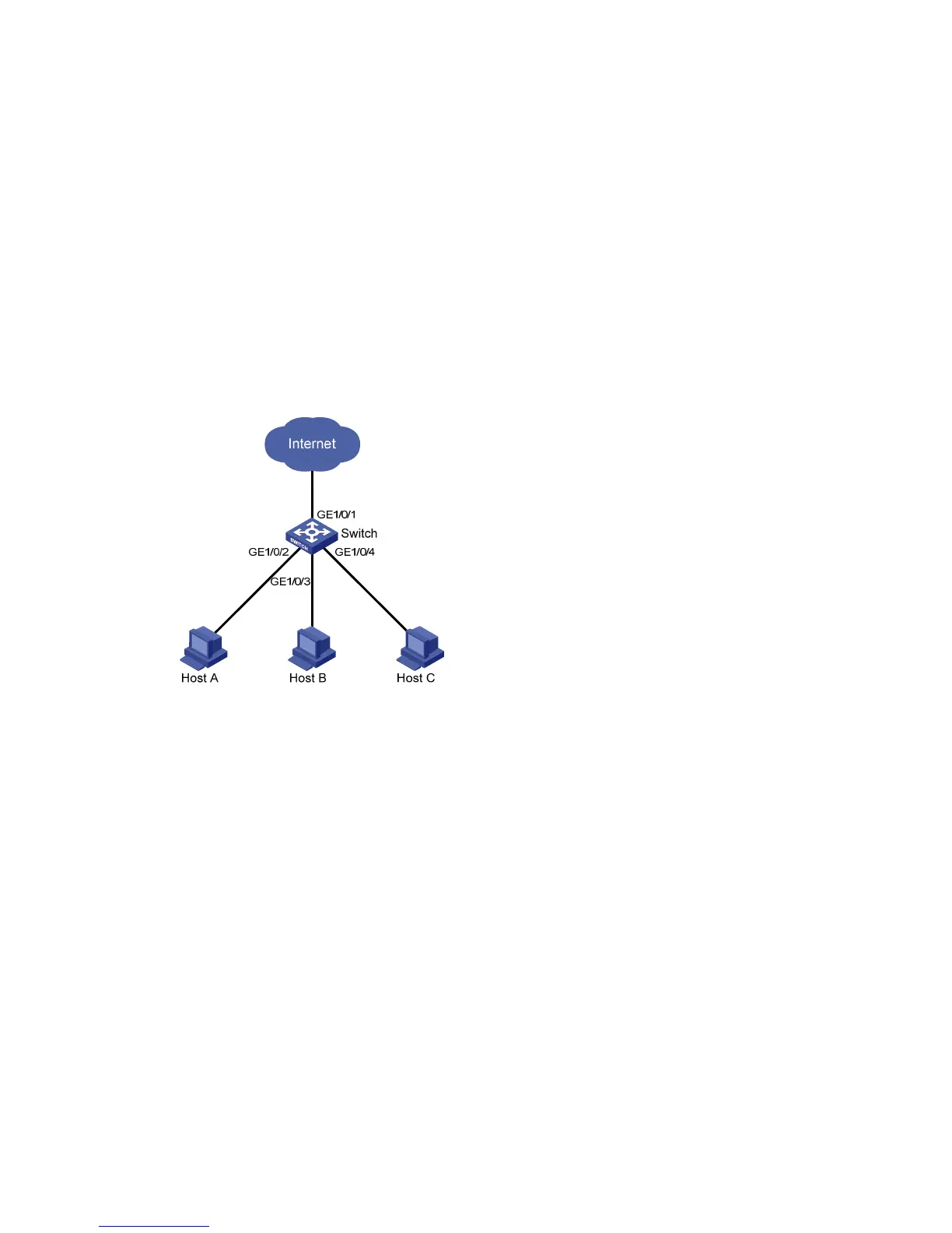
As shown in Figure 436:
• Campus network users Host A, Host B, and Host C are connected to GigabitEthernet 1/0/2,
GigabitEthernet 1/0/3, and GigabitEthernet 1/0/4 of Switch.
• Switch is connected to the external network through GigabitEthernet 1/0/1.
• GigabitEthernet 1/0/1, GigabitEthernet 1/0/2, GigabitEthernet 1/0/3, and GigabitEthernet
1/0/4 belong to the same VLAN.
Configure Host A, Host B, and Host C so that they can access the external network but are isolated from
one another at Layer 2.
Figure 436 Networking diagram
Configuring the switch
1. Assign ports GigabitEthernet 1/0/2, GigabitEthernet 1/0/3, and GigabitEthernet 1/0/4 to the
isolation group:
a. Select Security > Port Isolate Group from the navigation tree.
b. Click the Port Setup tab.
c. Select Isolated port for Config Type.
d. Select 2, 3, 4 on the chassis front panel. 2, 3, 4 represent ports GigabitEthernet 1/0/2,
GigabitEthernet 1/0/3, and GigabitEthernet 1/0/4, respectively.

 Loading...