287
IPv6 static route configuration example
Network requirements
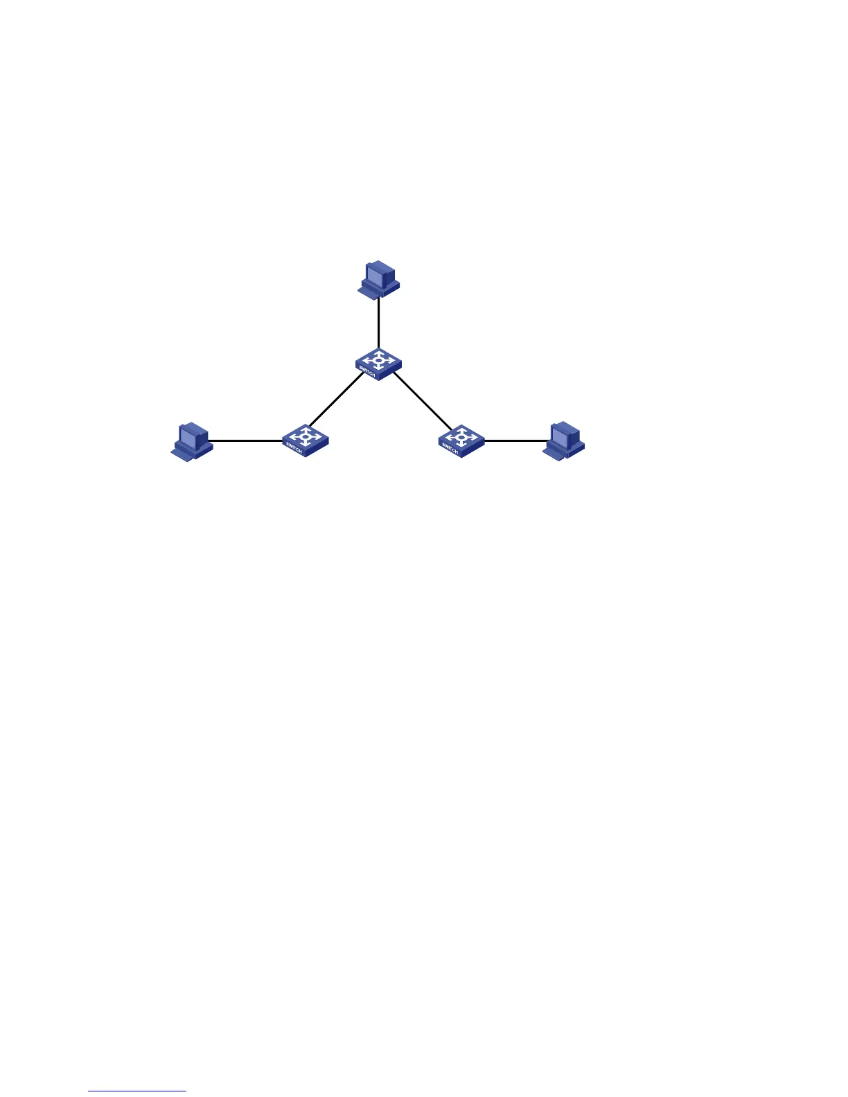
As shown in Figure 262, configure IPv6 static routes on Switch A, Switch B, and Switch C for any two
hosts to communicate with each other.
Figure 262 Network diagram
Configuration considerations
On Switch A, configure a default route with Switch B as the next hop.
On Switch B, configure one static route with Switch A as the next hop and the other with Switch C as the
next hop.
On Switch C, configure a default route with Switch B as the next hop.
Configuration procedure
1. Configure a default route to Switch B on Switch A:
a. Select Network > IPv6 Routing from the navigation tree of Switch A.
b. Click the Create tab.
c. Enter :: for Destination IP Address, select 0 from the Prefix Length list, and enter 4::2 for Next
Hop.
d. Click Apply.
Vlan-int400
2::1/64
Host B 2::2/64
Vlan-int200
4::2/64
Vlan-int300
5::2/64
Vlan-int200
4::1/64
Vlan-int300
5::1/64
Vlan-int500
3::1/64
Vlan-int100
1::1/64
Host A 1::2/64
Host C 3::2/64
Switch B
Switch A
Switch C

 Loading...