286
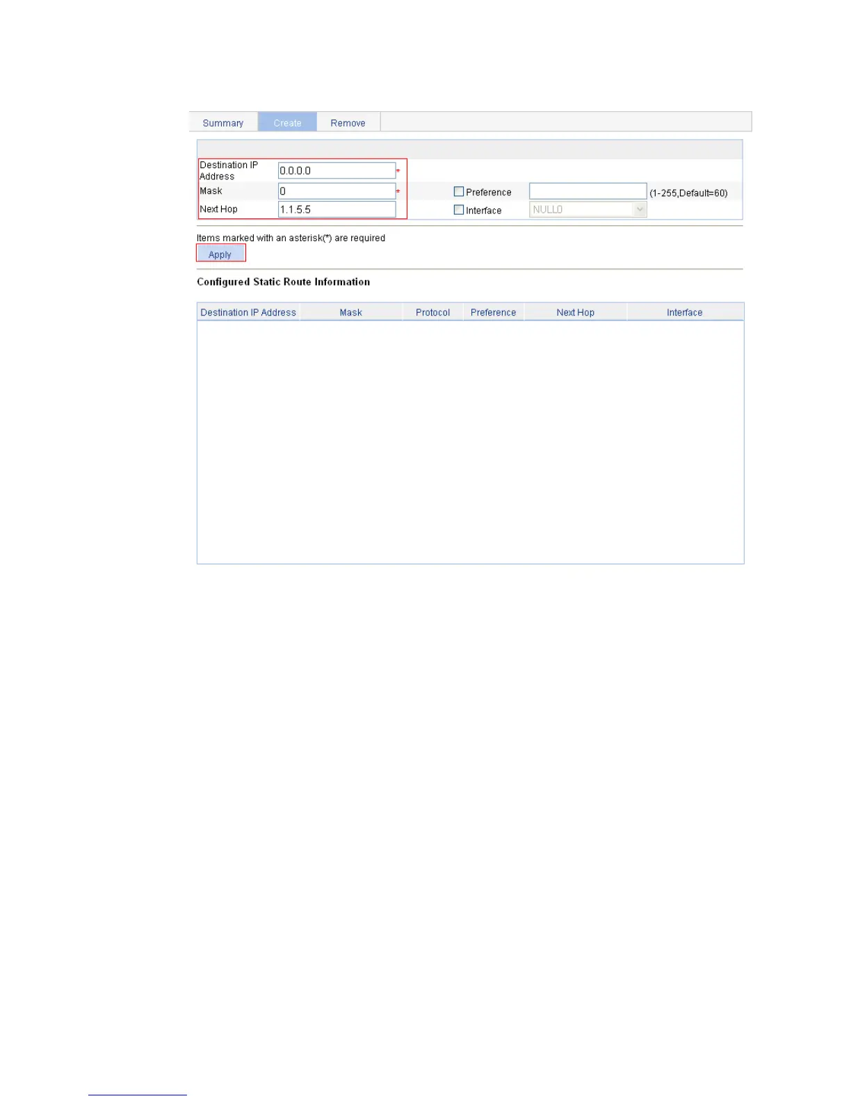
Figure 261 Configuring a default route
Verifying the configuration
1. Display the routing table.
Enter the IPv4 route page of Switch A, Switch B, and Switch C to verify that the newly configured
static routes are displayed as active routes on the pages.
2. Ping Host C from Host A (assuming both hosts run Windows XP):
C:\Documents and Settings\Administrator>ping 1.1.3.2
Pinging 1.1.3.2 with 32 bytes of data:
Reply from 1.1.3.2: bytes=32 time=1ms TTL=128
Reply from 1.1.3.2: bytes=32 time=1ms TTL=128
Reply from 1.1.3.2: bytes=32 time=1ms TTL=128
Reply from 1.1.3.2: bytes=32 time=1ms TTL=128
Ping statistics for 1.1.3.2:
Packets: Sent = 4, Received = 4, Lost = 0 (0% loss),
Approximate round trip times in milli-seconds:
Minimum = 1ms, Maximum = 1ms, Average = 1ms

 Loading...