273
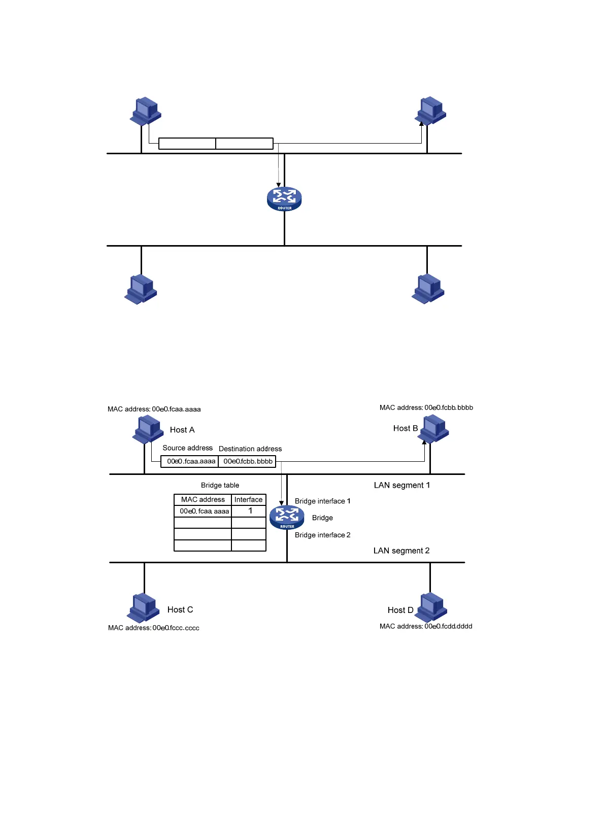
Figure 281 Host A sends an Ethernet frame to Host B on LAN 1
As the bridge receives the Ethernet frame on bridging interface 1, it determines that Host A is attached
to bridging interface 1 and creates a mapping between the MAC address of Host A and bridging
interface 1 in its bridge table, as shown in Figure 282.
Figure 282 The bridge determines that
Host A is attached to interface 1
When Host B responds to Host B, the bridge also hears the Ethernet frame from Host B. As the frame is
received on bridging interface 1, the bridge determines that Host B is also attached to bridging interface
1, and creates a mapping between the MAC address of Host B and bridging interface 1 in its bridge
table, as shown in Figure 283.
Bridge interface 2
MAC address: 00e0.fcaa.aaaa
MAC address: 00e0.fccc.cccc
MAC address: 00e0.fcdd.dddd
MAC address: 00e0.fcbb.bbbb
Host A
Host B
Host C Host D
LAN segment 2
LAN segment 1
Bridge
Bridge interface 1
00e0.fcaa.aaaa 00e0. fcbb.bbbb
Source address Destination address

 Loading...


