377
Item Descri
tion
GRE Key
Specify the key for the GRE tunnel interface. This configuration is to prevent the
tunnel ends from servicing or receiving packets from other places.
IMPORTANT:
The two ends of a tunnel must have the same key or have no key at the same time.
GRE Packet Checksum Enable or disable the GRE packet checksum function.
Keepalive
Enable or disable the GRE keepalive function.
With the GRE keepalive function enabled on a tunnel interface, the device sends
GRE keepalive packets from the tunnel interface periodically. If no response is
received from the peer within the specified interval, the device retransmits the
keepalive packet. If the device still receives no response from the peer after sending
the keepalive packet for the maximum number of attempts, the local tunnel interface
goes down and stays down until it receives a keepalive acknowledgement packet
from the peer.
Keepalive Interval
Specify the interval between sending the keepalive packets and the maximum
number of transmission attempts.
The two configuration items are available when you select Enable for the GRE
keepalive function.
Number of Retries
GRE over IPv4 tunnel configuration example
Network requirements
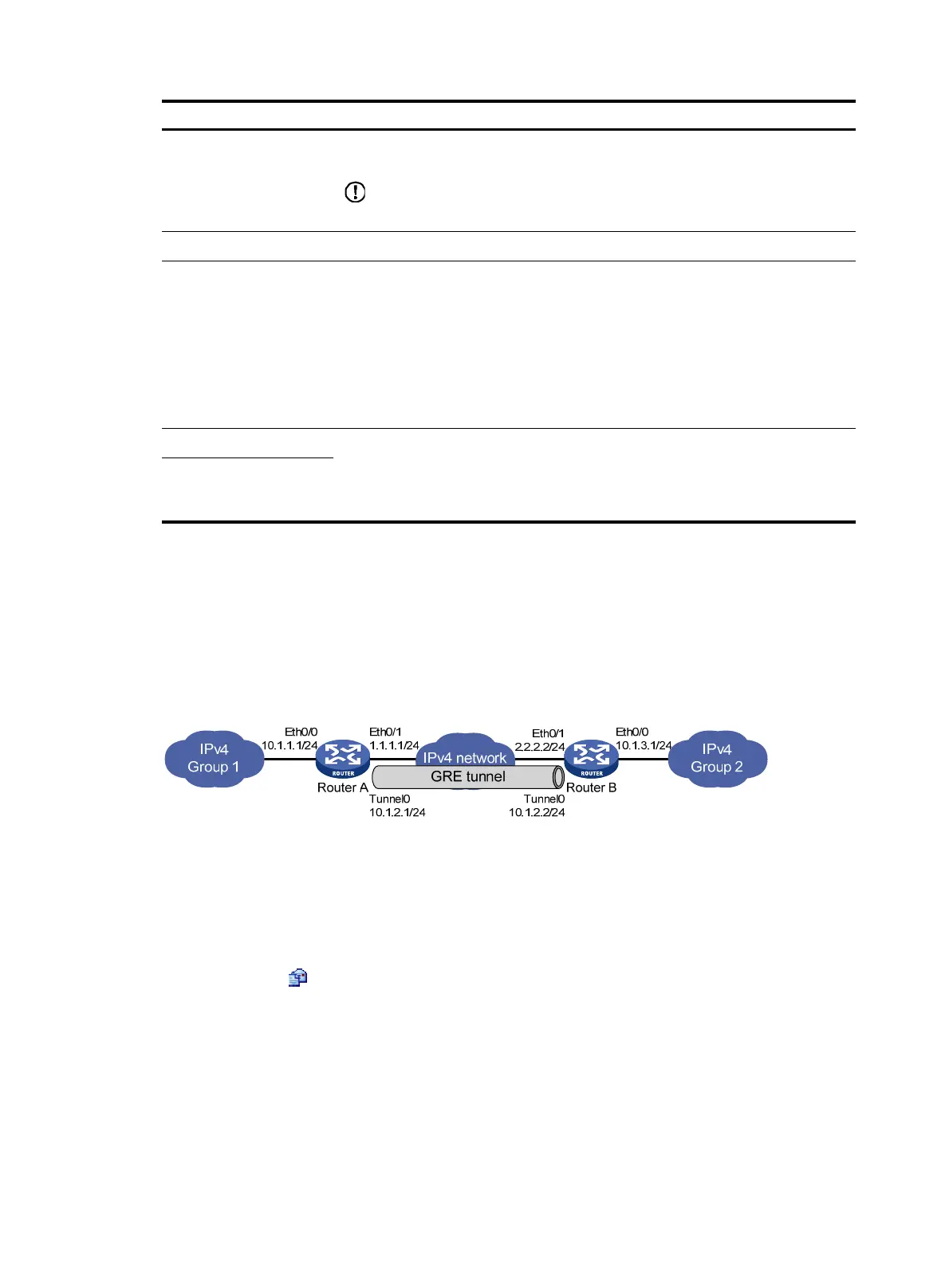
As shown in Figure 378, Router A and Router B are interconnected through the Internet. Two private IP
subnets Group 1 and Group 2 are interconnected through a GRE tunnel between Router A and Router B.
Figure 378 Network diagram
Before the configuration, make sure Router A and Router B can reach each other.
Configuring Router A
1. Configure an IPv4 address for interface Ethernet 0/0:
a. Select Interface Setup > WAN Interface Setup from the navigation tree of Router A.
b. Click the icon for interface Ethernet 0/0.
The WAN parameter configuration page for the interface appears, as shown in Figure 379.
c. Selec
t Manual for Connect Mode.
d. Enter IP address 10.1.1.1.
e. Select IP mask 24 (255.255.255.0).
f. Click Apply.

 Loading...


