301
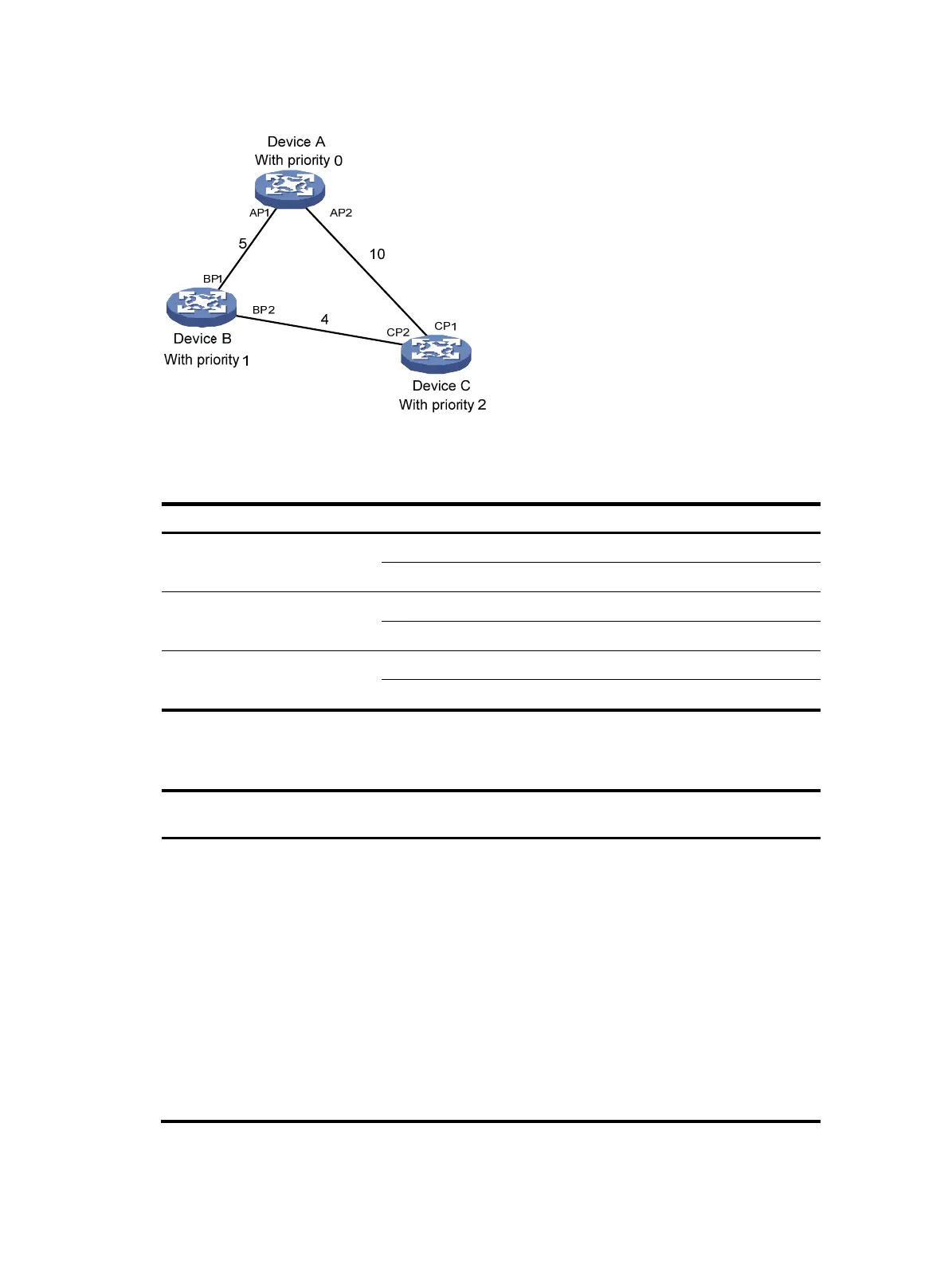
Figure 312 The STP algorithm
1. State initialization of each device.
Table 139 Initial state of each device
Device Port name
BPDU of
ort
Device A
AP1 {0, 0, 0, AP1}
AP2 {0, 0, 0, AP2}
Device B
BP1 {1, 0, 1, BP1}
BP2 {1, 0, 1, BP2}
Device C
CP1 {2, 0, 2, CP1}
CP2 {2, 0, 2, CP2}
2. BPDU comparisons on each device.
Table 140 Comparison process and result on each device
Device Comparison process
BPDU of port after
com
arison
Device A
• Port AP1 receives the configuration BPDU of Device B {1, 0,
1, BP1}. Device A finds that the configuration BPDU of the
local port {0, 0, 0, AP1} is superior to the received
configuration BPDU, and discards the received
configuration BPDU.
• Port AP2 receives the configuration BPDU of Device C {2, 0,
2, CP1}. Device A finds that the BPDU of the local port {0, 0,
0, AP2} is superior to the received configuration BPDU, and
discards the received configuration BPDU.
• Device A finds that both the root bridge and designated
bridge in the configuration BPDUs of all its ports are itself, so
it assumes itself to be the root bridge. It does not make any
change to the configuration BPDU of each port, and starts
sending out configuration BPDUs periodically.
AP1: {0, 0, 0, AP1}
AP2: {0, 0, 0, AP2}

 Loading...


