175
Selection of the root bridge
Initially, each STP-enabled device on the network assumes itself to be the root bridge, with the root bridge
ID being its own device ID. By exchanging configuration BPDUs, the devices compare their root bridge
IDs to elect the device with the smallest root bridge ID as the root bridge.
Selection of the root port and designated ports on a non-root device
Table 70 Selection of the root port and designated ports
Step Description
1
A non-root device regards the port on which it received the optimum configuration BPDU as the
root port.
2
Based on the configuration BPDU and the path cost of the root port, the device calculates a
designated port configuration BPDU for each of its other ports.
The root bridge ID is replaced with that of the configuration BPDU of the root port.
The root path cost is replaced with that of the configuration BPDU of the root port plus the path
cost of the root port.
The designated bridge ID is replaced with the ID of this device.
The designated port ID is replaced with the ID of this port.
3
The device compares the calculated configuration BPDU with the configuration BPDU on the port
whose port role is to be determined:
If the calculated configuration BPDU is superior, the device considers this port as the designated
port, replaces the configuration BPDU on the port with the calculated configuration BPDU, and
periodically sends out the calculated configuration BPDU.
If the configuration BPDU on the port is superior, the device blocks this port without updating its
configuration BPDU. The blocked port can receive BPDUs, but cannot send BPDUs or forward
data.
NOTE:
nated ports forward traffic, while other
ports are all in the blocked state to receive BPDUs but not to forward BPDUs or user traffic.
A tree-shape topology forms when the root bridge, root ports, and designated ports are selected.
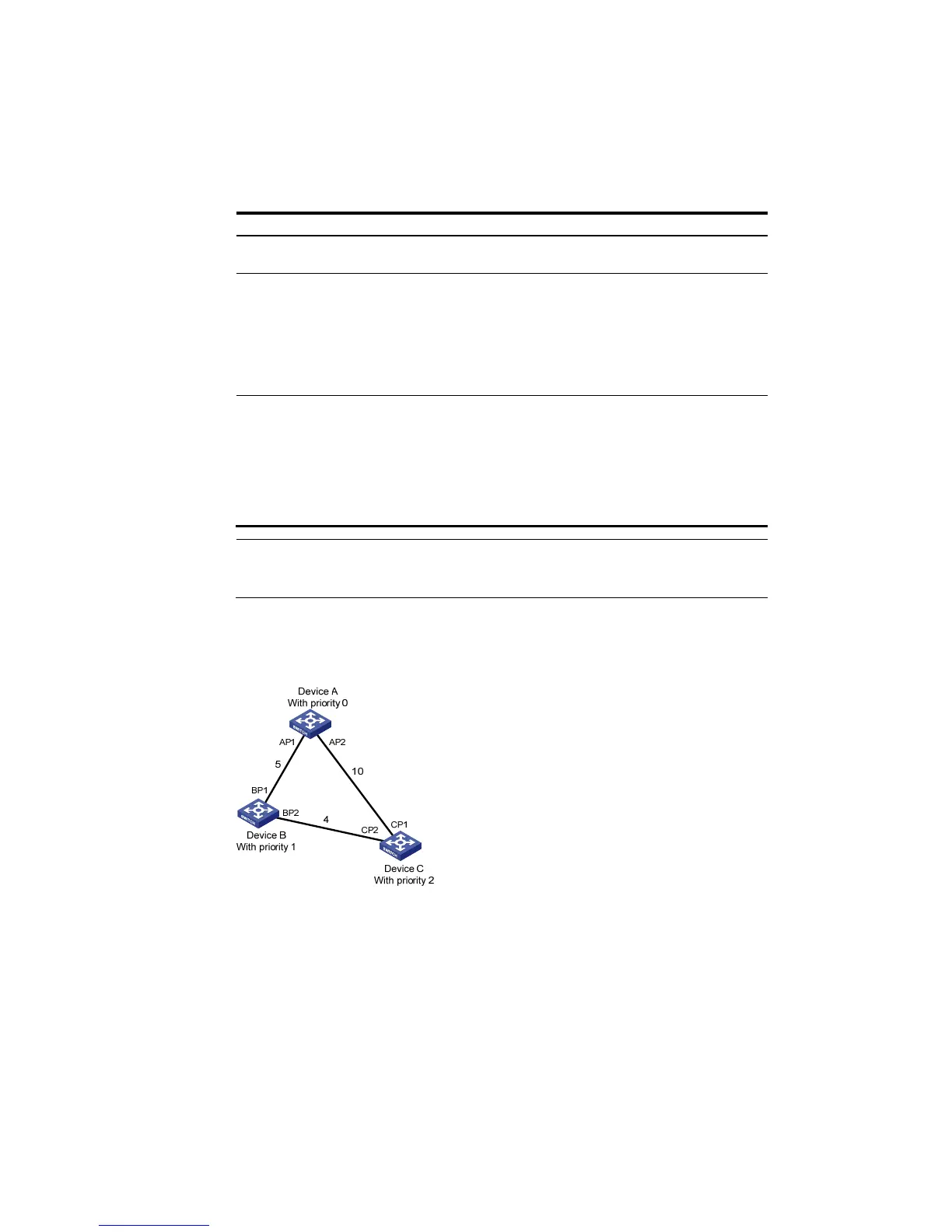
The following describes how the STP algorithm works.
Figure 162 Network diagram for the STP algorithm

 Loading...