Refer to the Intel Stratix 10 E-Tile Channel Placement Tool for details about possible
channel placement based on system requirements.
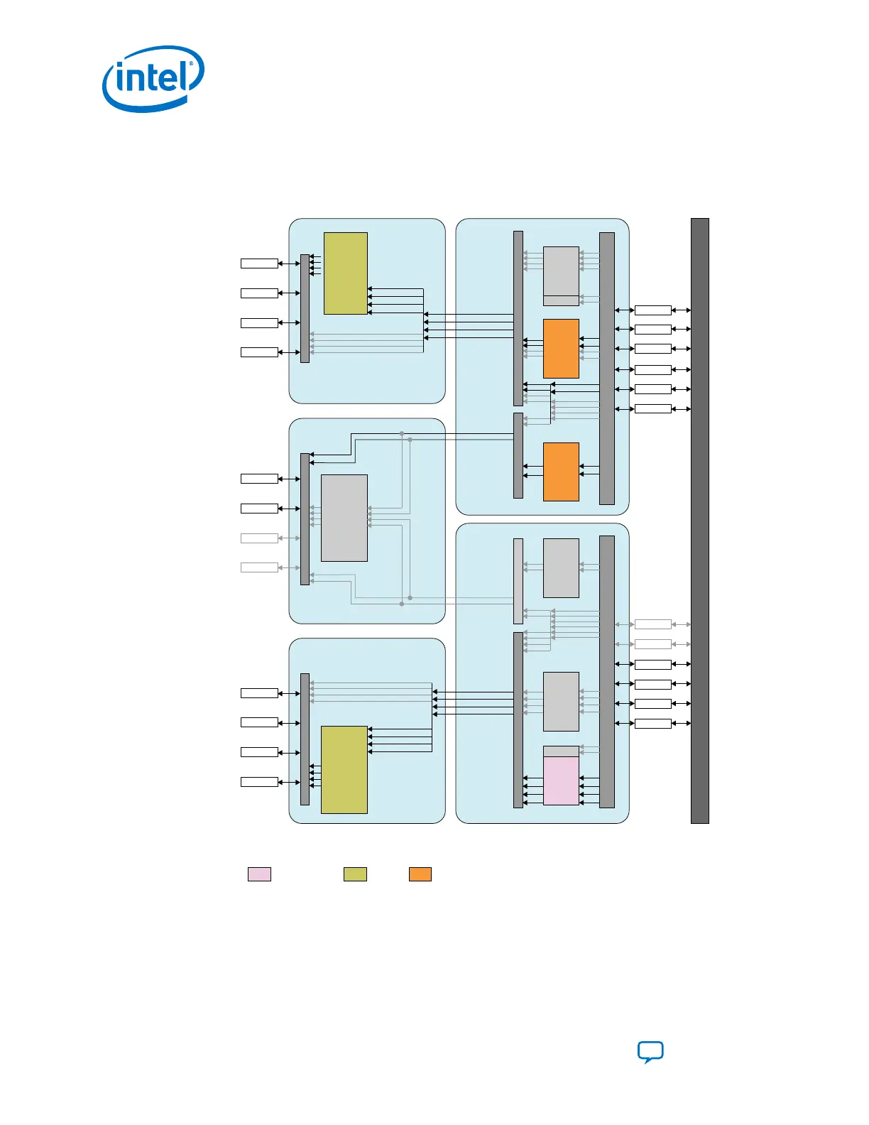
Figure 48. Channel Configurations Implementing Various FEC Modes
Check Table 38 on page 82 for configuration description.
EHIP_LANE
x4
(10G /25G)
MAC + PCS
EHIP_LANE
x2
(10G /25G)
MAC + PCS
EHIP_LANE
x2
(10G /25G)
MAC + PCS
EHIP_LANE
x4
(10G /25G)
MAC + PCS
P
T
P
EHIP_CORE
(100G MAC
+ PCS)
EHIP_CORE
(100G MAC
+ PCS)
P
T
P
FEC
(528, 514) or
(544, 514)
(Aggregate:
100G)
(Fractured:
25G)
FEC
(528, 514)
(Fractured:
25G)
FEC
(528, 514)
or (544, 514)
(Aggregate:
100G)
(Fractured:
25G)
EHIP_TOP
EHIP_TOP
PMA Direct
PMA Direct
RS-FEC
Legend:
= EHIP_CORE
= FEC
= EHIP_LANE
Interconnect
Interconnect Interconnect
Interconnect
Interconnect
Interconnect
InterconnectInterconnectInterconnect
FPGA Core
11
10
9
8
7
6
5
4
3
2
1
0
RS-FEC
RS-FEC
PMA CH0
PMA CH1
PMA CH2
PMA CH3
PMA CH4
PMA CH5
PMA CH6
PMA CH7
PMA CH8
PMA CH9
PMA CH10
PMA CH11
8
9
10
11
11
10
9
8
76
11
10
9
8
7
6
76
10 32
10 32
10 32
10 32
Related Information
Intel Stratix 10 E-Tile Channel Placement Tool
3. Intel Stratix 10 E-Tile Transceiver PHY Architecture
UG-20056 | 2019.02.04
Intel
®
Stratix
®
10 E-Tile Transceiver PHY User Guide
Send Feedback
84