Settings
228
Pos: 34.81.8 /Überschr iften/Überschr iften 3/K-O/Nullste llung (VFS-System) @ 107\ mod_1334225251167_78. docx @ 964914 @ 3 @ 1
11.11.2 Zero position (VFS system)
Pos: 34.81.9 /BA/E instellungen/Großpac kenpresse/Variab les Füllsystem VFS/Bi G PACK 4x4/Nullstellung Bi ld @ 107\mod_133422532 7515_78.docx @ 964942 @ @ 1
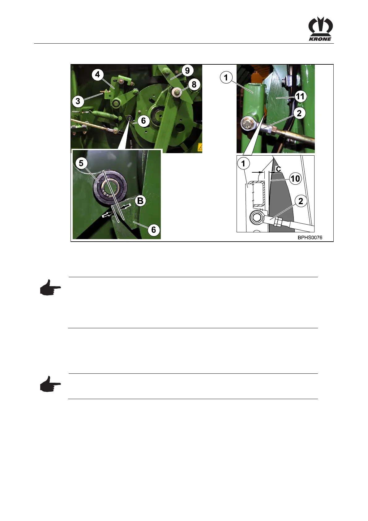
Fig. 167
Pos: 34.81.10 /BA/Ei nstellungen/Großpac kenpresse/Variab les Füllsystem VFS/Bi G PACK 4x4/Nullstellun g Text @ 107\mod_133422537 4626_78.docx @ 964970 @ @ 1
Manually rotate the packer in the direction of operation by turning the flywheel until the roller
(8) has engaged in the zeroizing device (9). (The VF system is now in the zero position.)
Note
The zero position has been correctly set when
• the anvil (4) is positioned on the set screw (3)
• the middle of the roller of the grooved ball bearing (5) is positioned B = 10 mm from
the tip of the trigger cam disc (6) on the trigger cam disc
• the feeler rocker (1) is C = 10 – 15 mm from the edge of the packer tray (11)
Check settings and if required correct as follows:
• Adjust the set screw (3) until the middle of the roller of the grooved ball bearing (5) is
positioned B = 10 mm from the tip of the trigger cam disc (6) on the trigger cam disc
Note
If dimension B cannot be set, check and, if required, adjust the absorbing mechanism
(see Settings section “Adjusting the absorbing mechanism”).
• Adjust the threaded rod (2) until the feeler rocker (1) is C = 10 – 15 mm from the edge of
the packer tray (11)
Pos: 34.81.11 /BA/---------------Seitenumbruch---------------- @ 0\mod_1196175311226_0.doc x @ 4165 @ 3 @ 1