Maintenance – lubrication
272
Pos: 36.54.13 /Übersc hriften/Überschr iften 2/A-E/Abschmier en der Gelenkwelle @ 0\m od_1197359496183_78.d ocx @ 18251 @ 2 @ 1
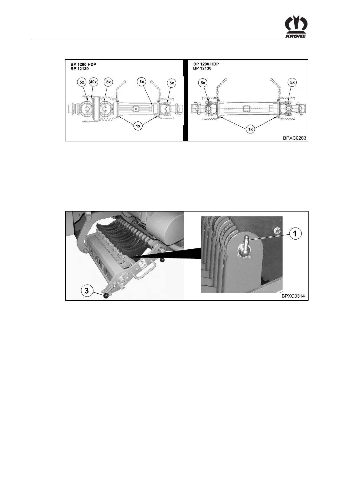
14.4 Lubricating the PTO shaft
Pos: 36.54.14 /BA/W artung/Gelenkwelle schmier enAbschmieren Gelenk welle Bild BPP 1290 HDP / 12130 @ 24\mod_12 41688105086_78. docx @ 247685 @ @ 1
Fig. 198
Pos: 36.54.15 /BA/W artung/Großpackenpr essen/Schmierung / Sc hmierplan/Bezeichnun g der Gelenkwelle Haup tantrieb / Gelenkwelle Sc hwungrad @ 24\mod_12416881 66695_78.docx @ 247710 @ 2 @ 1
Main drive universal shaft Flywheel universal shaft
Pos: 36.54.16 /BA/W artung/Gelenkwelle sch mierenAbschmieren Gelenkwelle 1290 HDP @ 24\mod_12 41688603680_78.doc x @ 247738 @ 3 @ 1
Universal shafts must be lubricated with multi-purpose grease every 50 hours at designated
lubrication points. The figure above shows the number of pump pulses per lubrication point.
Follow the operating instructions of the universal shaft manufacturer.
Pos: 36.54.17 /BA/W artung/Großpackenpr essen/Schmierung / Sc hmierplan/Laufrol len der Messerhebel absc hmieren @ 24\mod_1241695 903648_78.docx @ 247898 @ @ 1
14.5 Lubricating the rollers for the blade lever
Fig. 199
• Lower the cutting system with the tractor hydraulics (with the comfort electronics system:
Activate the tractor hydraulics and hold down “Lower blade bar” on the control unit display
or on the machine buttons until the cutting system is lowered all the way down)
• Remove the ignition key and turn off the electrical system on the control unit
• Apply the flywheel brake
• Secure the tractor and machine against rolling
• Unlock the cutting system half and remove it as far as the stop (right hand and left hand
machine side)
• Lubricate all grease nipples for the rollers of the blade levers
• Push in the half of the cutting system on the side (right hand and left hand side of the
machine) until the locking lever (3) snaps into place by itself
• Raise the cutting system hydraulically
Pos: 36.54.18 /BA/---------------Seitenumbruch---------------- @ 0\mod_1196175311226_0.doc x @ 4165 @ @ 1






 To Next Page