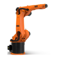
4.11.5.4 Stopping distances and stopping times, STOP 1, A3
Fig. 4-101: Stopping distances for STOP 1, axis 3
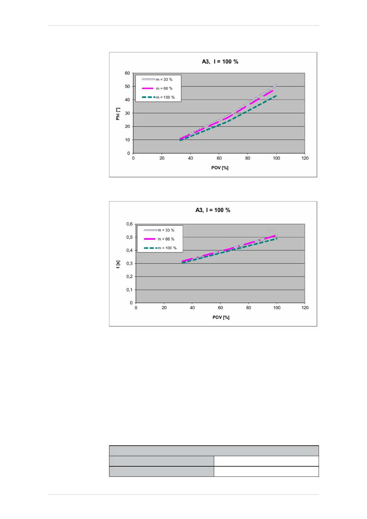
Fig. 4-102: Stopping times for STOP 1, axis 3
4.11.6 Stopping distances and times, KR 70 R2100 and KR 70 R2100 F
4.11.6.1 Stopping distances and stopping times, STOP 0, A1 to A3
The table shows the stopping distances and stopping times after a
STOP 0 (category 0 stop) is triggered. The values refer to the following
configuration:
• Extension l = 100%
• Program override POV = 100%
• Mass m = maximum load (rated load + supplementary load on arm)
Stopping distance
A1 37.62 °
A2 21.05 °
KR IONTEC
152/344 | www.kuka.com MA KR IONTEC V4 | Issued: 11.05.2021
Technical data

 Loading...