NOTICE
When installing the in-line wrist, it must be ensured that the toothing
of the in-line wrist and connecting shafts is not damaged. Increased
wear and premature failure may result.
9.5.3.7 Installing motor A6 and in-line wrist
Procedure
1. If a new motor is to be installed, remove any corrosion protection prior
to installation.
2. Clean the toothing on connecting shaft A6 and check for wear.
3. Grease the involute toothing.
4. Insert the sinuous spring and fit motor A6 into the in-line wrist. Do not
tilt while fitting.
5. Insert 4 M5x14-8.8-A2K Allen screws and tighten with a torque wrench
in diagonally opposite sequence. Increase the tightening torque to the
specified value in several stages.
6. Clean the surface between the in-line wrist and the arm extension and
apply a thin but continuous coat of Drei Bond 5204 HV adhesive.
7. Plug connectors XM6 and XP6 into the right-angle connectors.
8. Place the in-line wrist on the arm extension, taking care not to tilt it.
9. Insert 16 M6x35-8.8-A2K Allen screws into the arm extension and
tighten with a torque wrench in diagonally opposite sequence.
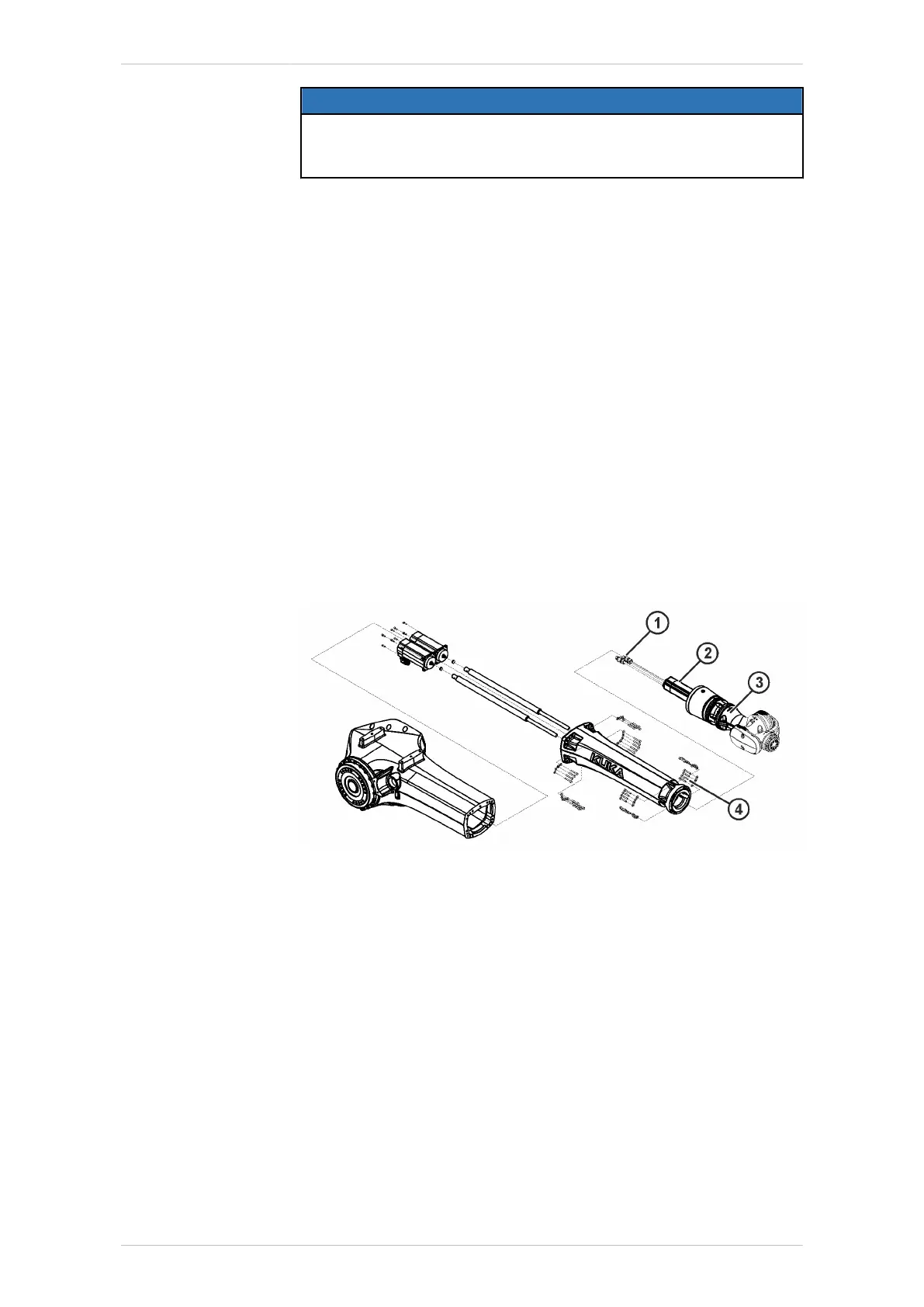
Fig. 9-38: KR 20 R3100 – Removing/installing motor A6
1 Connectors XM6 and XP6
2 Motor A6
3 In-line wrist
4 M6x35-8.8-A2K Allen screws with conical spring washers (16x)
10. Screw cable holder for motor cable A6 to the arm extension using 2
M6x12-8.8-A2K Allen screws.
11. Clean connecting shafts A4 and A5 and grease with Microlube GL
261.
Guide the connecting shafts into the arm extension with a mandrel (or
on motor shaft without sinuous spring) and fit them onto the corre-
sponding shafts of the in-line wrist.
KR IONTEC
MA KR IONTEC V4 | Issued: 11.05.2021 www.kuka.com | 279/344
Repair

 Loading...

