2.2 Description of the manipulator
Overview
The manipulators (robot arm and electrical installations) (>>> Fig. 2-2) of
the KR IONTEC robot family are designed as 6-axis jointed-arm kinematic
systems. They consist of the following principal components:
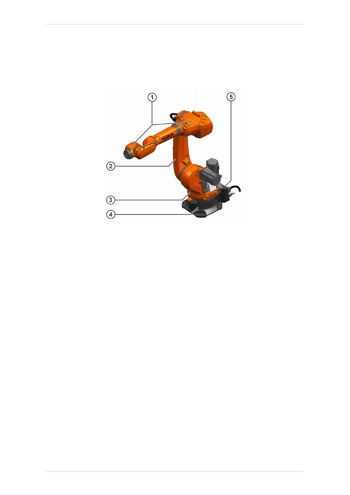
Fig. 2-2: Main assemblies of the manipulator
1 In-line wrist/arm
2 Link arm
3 Rotating column
4 Base frame
5 Electrical installations
Axes 1 to 3 are equipped with end stops. These serve only as machine
protection. There are two options available for personnel protection:
• The Safe Robot functionality of the controller
• The use of mechanical axis limitations for axes 1 to 3 (optional).
In-line wrist/arm
The robot is equipped with a three-axis in-line wrist / arm combination.
This in-line wrist / arm combination is screwed directly to the link arm of
the robot via gear unit A3. End effectors are attached to the mounting
flange of axis 6. Axes A1 to A6 have a measuring device, through which
the mechanical zero of the respective axis can be checked by means of
an electronic probe (MEMD) and transferred to the controller. Directions of
rotation, axis data and permissible loads can be found in the chapter
(>>> 4 "Technical data" Page 33). The in-line wrist is driven by the mo-
tors inside the in-line wrist.
There is an interface on the arm for fastening supplementary loads.
The mounting flange conforms, with minimal deviations, to ISO 9409-1:
2004
KR IONTEC
16/344 | www.kuka.com MA KR IONTEC V4 | Issued: 11.05.2021
Product description

 Loading...

