Insertion of motor can be facilitated by turning it gently about its ro-
tational axis.
7. Insert 4 M10x25-8.8-A2K Allen screws.
8. Tighten 4 M10x25-8.8-A2K Allen screws with a torque wrench in diag-
onally opposite sequence. Increase the tightening torque to the speci-
fied value in several stages.
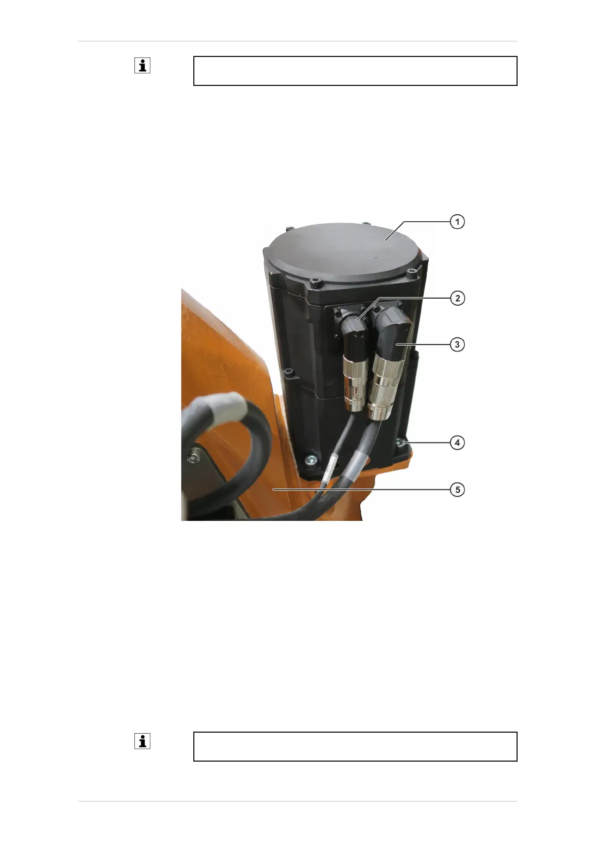
9. Plug connectors XM1 and XP1 into the right-angle connectors. The
pins and coding elements of the connectors must be taken into con-
sideration. When inserting the connectors, turn them until they clearly
lock into the coding elements (twist-proof).
Fig. 9-2: Motor A1
1 Motor A1
2 Connector XP1
3 Connector XM1
4 M10x25-8.8-A2K Allen screw
5 Rotating column
9.1.3 Concluding work
The following concluding work must be carried out:
• Move A1 of the robot and look out for irregularities.
• Carry out mastering of A1.
Detailed information about mastering is contained in the operating
and programming instructions for end users or system integrators.
KR IONTEC
232/344 | www.kuka.com MA KR IONTEC V4 | Issued: 11.05.2021
Repair

 Loading...

