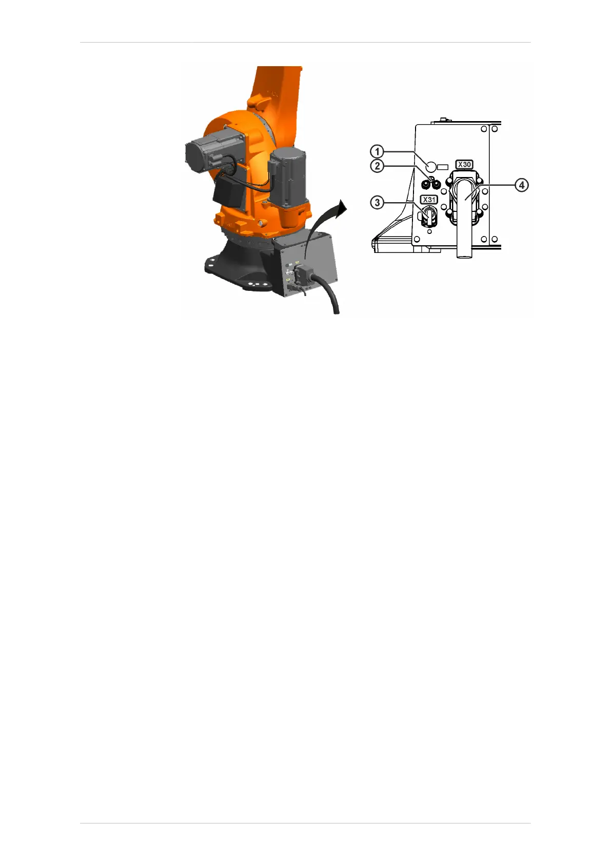
Fig. 7-9: Connecting the connecting cables
1 Connection for sealing air (for Foundry only)
2 Ground conductor (2x)
3 Data cable X31
4 Motor cable X30
7.3.5 Concluding work
The following concluding work must be carried out:
• If applicable, mount the tool.
• Start up the robot system in accordance with the chapter “Start-up and
recommissioning” in the operating instructions for the robot controller.
• Put the robot system into operation in accordance with the chapter
“Start-up and recommissioning” of the operating and programming in-
structions for the KUKA System Software (KSS).
7.4 Description of the connecting cables
Configuration
The connecting cables are used to transfer power and data between the
robot controller and the robot.
The connecting cables comprise:
• Motor cable
• Control cable
Interface
For the connection of the connecting cables between the robot controller
and the robot, the following connectors are available on the junction box-
es.
KR IONTEC
MA KR IONTEC V4 | Issued: 11.05.2021 www.kuka.com | 183/344
Start-up and recommissioning

 Loading...

