3. Release and carefully lift out motor A1, taking care not to tilt it.
4. Cover the aperture on gear unit input shaft A1 and protect it against
fouling.
5. If the motor is not to be reinstalled, it must be disposed of properly or
protected against corrosion before being put into storage.
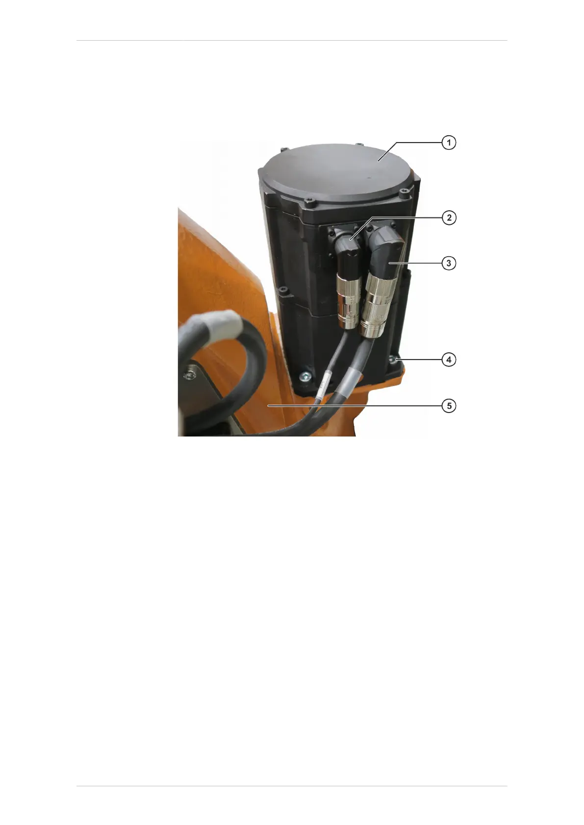
Fig. 9-1: Motor A1
1 Motor A1
2 Connector XP1
3 Connector XM1
4 M10x25-8.8-A2K Allen screw
5 Rotating column
9.1.2 Installing motor A1
Procedure
1. If a new motor is to be installed, remove any corrosion protection it
may have prior to installation (>>> 9.1.2 "Installing motor A1"
Page 231).
2. Clean the involute toothing of motor A1 and gear unit input shaft A1
before installation and apply a thin but continuous coat of Microlube
GL 261 grease.
3. Clean the mounting surface for motor A1.
4. Check the condition of the O-ring on the motor shaft; exchange if nec-
essary.
5. Position right-angle connectors XM1 and XP1 as shown.
6. Insert motor A1, taking care not to tilt it.
KR IONTEC
MA KR IONTEC V4 | Issued: 11.05.2021 www.kuka.com | 231/344
Repair

 Loading...

