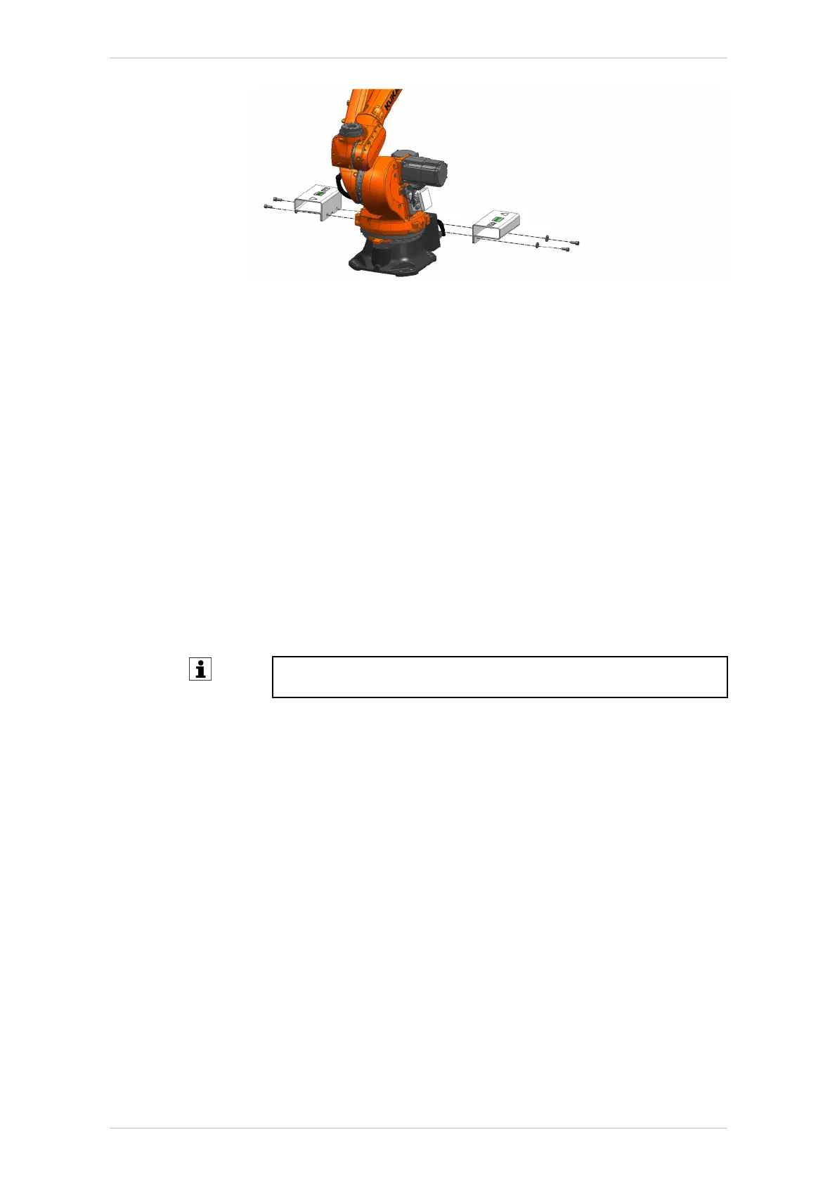
Fig. 7-8: Removing the fork slots
7.3.4 Connecting the connecting cables
Procedure
1. Fasten the ground conductor between the robot controller and the ro-
bot to the ground conductor connection with 1 M8 hexagon nut includ-
ing conical spring washer; tightening torque M
A
= 15.0 Nm.
2. Optionally, fasten the ground conductor between the system compo-
nent and the robot to the ground conductor connection with 1 M8 hex-
agon nut including conical spring washer; tightening torque
M
A
= 15.0 Nm.
3. Connect motor cable X30 and data cable X31 (>>> Fig. 7-9).
When connecting the motor and data cable connectors, it must be en-
sured that the connectors on the controller and on the robot are
locked correctly.
4. Check the equipotential bonding in accordance with VDE 0100 and
EN 60204-1.
Further information is contained in the operating and assembly in-
structions of the robot controller.
5. Enter the installation position of the robot in WorkVisual. The default
installation position is the floor.
KR IONTEC
182/344 | www.kuka.com MA KR IONTEC V4 | Issued: 11.05.2021
Start-up and recommissioning

 Loading...

