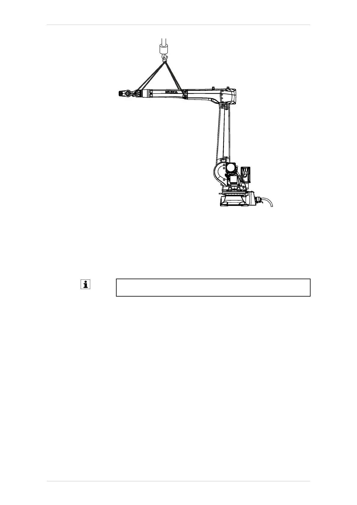
Fig. 9-54: Securing robot arm
9.5.4.9 Concluding work
The following concluding work must be carried out:
• Move A4, A5 and A6 of the robot and look out for irregularities.
• Carry out mastering of A4, A5 and A6.
Detailed information about mastering is contained in the operating
and programming instructions for end users or system integrators.
• Test the program in Manual Reduced Velocity mode (T1).
9.6 Description of the electrical installations
Overview
The electrical installations of the robot consist of:
• Cable set
• Micro RDC box
Description
The electrical installations consist of the cable set from A1 to A3 with mi-
cro RDC as well as the cable set from A4 to A6. The cable sets include
all the supply and control cables for the motors of axes 1 to 6 as well as
the cables for the protective circuit.
Micro RDCs are explained in more detail in the operating instructions of
the robot controller.
The interface for connecting the connecting cables to the robot is located
on the base frame at the rear of the robot. The interfaces X30, X31 and
ground conductor (PE) bolts are located on interface A1. The connecting
KR IONTEC
296/344 | www.kuka.com MA KR IONTEC V4 | Issued: 11.05.2021
Repair

 Loading...

