cables from the controller – such as motor cable X30, data cable X31 and
the ground conductor – are connected here by means of connectors.
The selected routing of cables and hoses within the robot arm ensures
that they are guided without strain or kinking throughout the entire motion
range of the robot
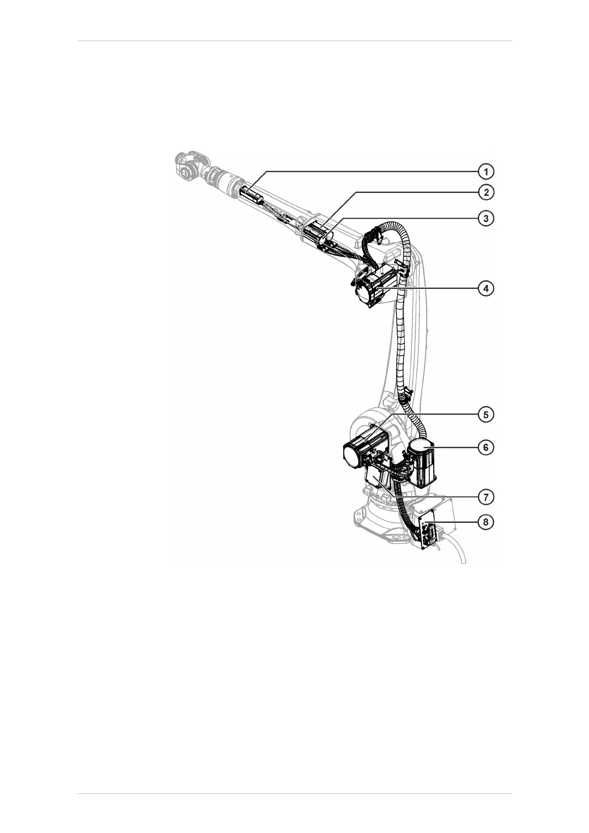
The following diagram gives an overview of the installation and routing of
the cables in (>>> Fig. 9-56).
Fig. 9-55: KR 20 R3100 electrical installations, overview
1 Motor A6 5 Motor A2
2 Motor A5 6 Motor A1
3 Motor A4 7 Micro RDC box
4 Motor A3 8 Interface A1
KR IONTEC
MA KR IONTEC V4 | Issued: 11.05.2021 www.kuka.com | 297/344
Repair

 Loading...

