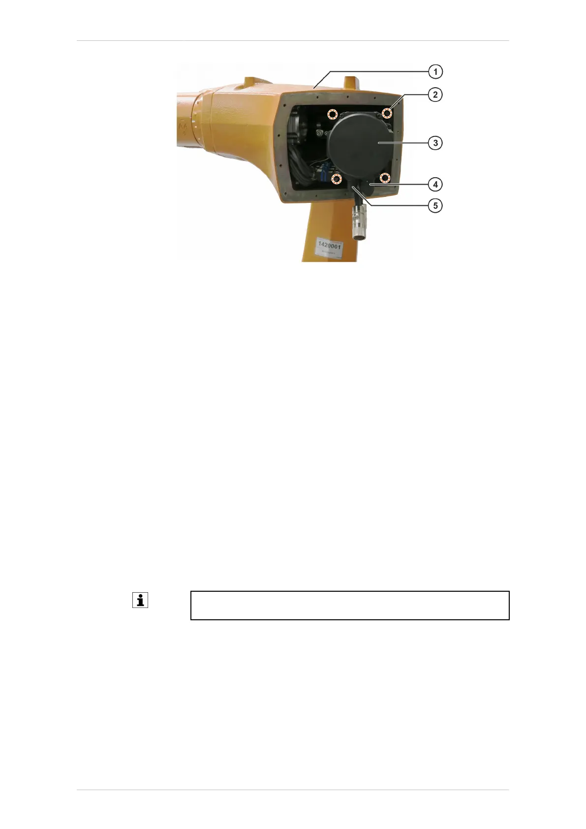
Fig. 9-9: Motor A3
1 Robot arm
2 M8x22-8.8-A2K Allen screw
3 Motor A3
4 Connector XM3
5 Connector XP3
9.3.4 Installing motor A3
Procedure
1. If a new motor is to be installed, remove any corrosion protection it
may have prior to installation (>>> 9.3.4 "Installing motor A3"
Page 243).
2. Clean the involute toothing of motor A3 and gear unit input shaft A3
before installation and apply a thin but continuous coat of Microlube
GL 261 grease.
3. Clean the mounting surface for motor A3.
4. Check the condition of the O-ring on the motor shaft; exchange if nec-
essary.
5. Position right-angle connectors XM3 and XP3 as shown.
6. Insert motor A3, taking care not to tilt it.
Insertion of motor can be facilitated by turning it gently about its ro-
tational axis.
7. Insert 4 M8x22-8.8-A2K Allen screws.
8. Tighten 4 M8x22-8.8-A2K Allen screws with a torque wrench in diago-
nally opposite sequence. Increase the tightening torque to the speci-
fied value in several stages.
9. Plug connectors XM3 and XP3 into the right-angle connectors. The
pins and coding elements of the connectors must be taken into con-
sideration. When inserting the connectors, turn them until they clearly
lock into the coding elements (twist-proof).
KR IONTEC
MA KR IONTEC V4 | Issued: 11.05.2021 www.kuka.com | 243/344
Repair
 Loading...