5. Remove 3 M4x10-8.8 Allen screws with washers and 1 M4x16-8.8 Al-
len screw with washer from the gripper holder (gripper side).
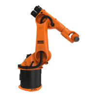
Fig. 14-1: Exchanging the gripper
1 M4x16-8.8 Allen screw (1x)
2 M4x10-8.8 Allen screw (3x)
3 Pneumatic line
4 Push-in coupling
5 Gripper
6 Proximity switches
14.3.1.2 Installing the basic gripper
Precondition
• The main switch is switched off and secured to prevent unauthorized
persons from switching it on again.
• The robot is depressurized.
Procedure
1. Fasten the gripper with 3 M4x10-8.8 Allen screws with washers and 1
M4x16-8.8 Allen screw with washer to the gripper holder (gripper
side).
2. Connect the pneumatic line at the push-in coupling.
3. Connect the proximity switches at the markings.
4. Check the function and position (I/O) of the proximity switches on the
smartPAD.
ready2_educate
120/154 | www.kuka.com BA ready2_educate V8 | Issued: 05.09.2018
Repair