3.4.6 Mounting plate, electrical system
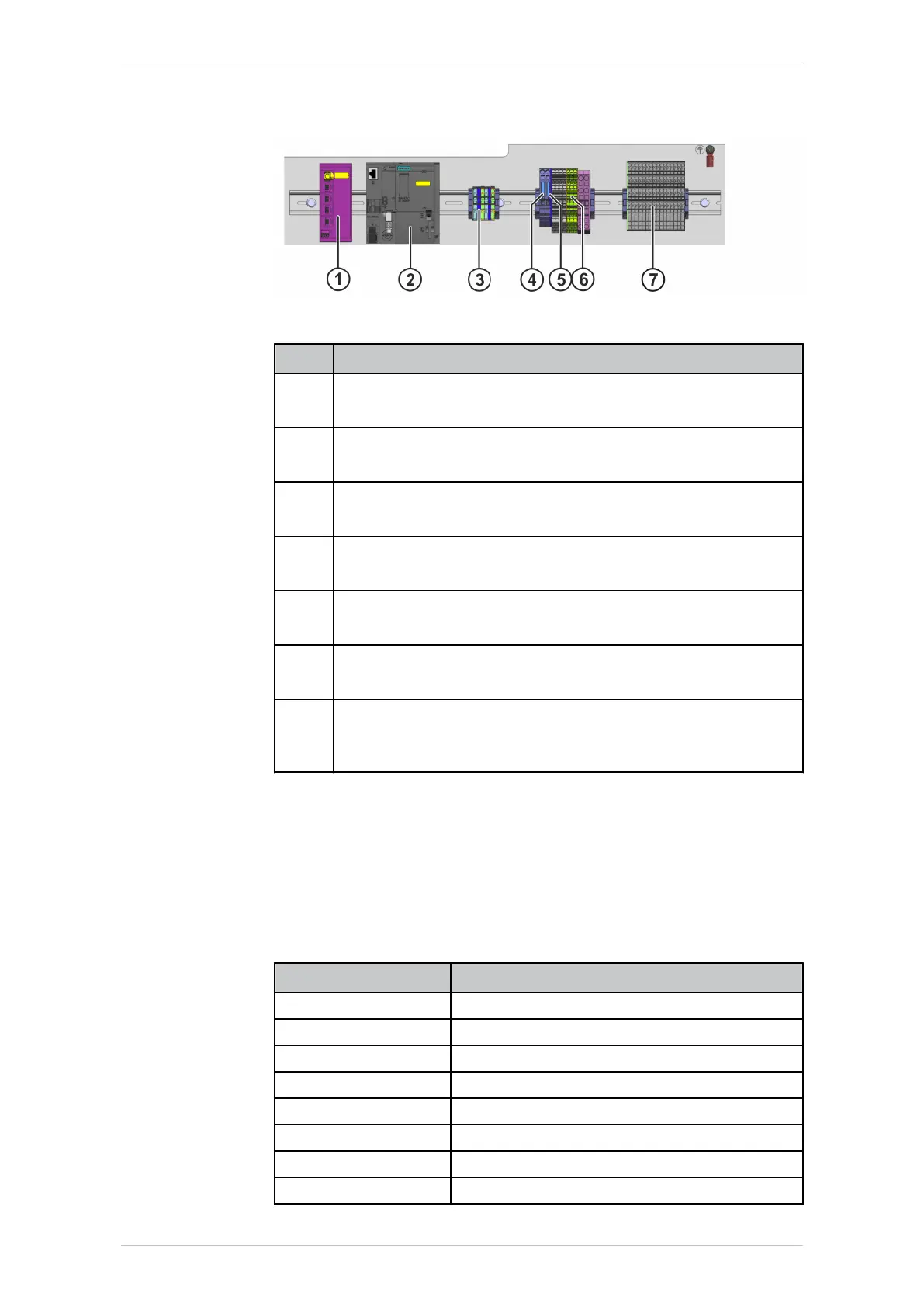
Fig. 3-23: Mounting plate, electrical system
Item
Description
1 -A10
Switch
2 -A1
CPU; PLC
3 X0
Power supply, 200-240 V, 50-60 Hz
4 F1.5.1/1.5.2
Fuses, 4A
5 F1.5.3
Fuse, 1A
6 X1
Power supply, 24 V, PE connection
7 X1B
Connections for gripper pressure valve, E-STOP, acknowledg-
ing operator safety, safety switches, Profinet
3.4.7 Media interface
Description
For electrical and pneumatic application expansions, this variant is equip-
ped with the media interface (power supply, air, digital I/Os and PROFINet
bus).
The power supply interface has the following pin assignment:
Pin Assignment
1 - 8 Digital inputs DI9 to DI16
9 - 10 Not assigned
11 - 18 Digital outputs DO9 to DO16
19 -20 Not assigned
21 24V DC power supply
22 Not assigned
23 - 24 0 V DC power supply
25 Not assigned
ready2_educate
BA ready2_educate V8 | Issued: 05.09.2018 www.kuka.com | 27/154
Product description