Procedure
1. Install the ready2_educate cell and check for any damage caused dur-
ing transportation.
2. Check that fuses, contactors and boards are fitted securely.
3. Secure any modules that have come loose.
4. Main switch is in the 0 (OFF) position.
5. Close the compressed air shut-off valve.
6. Connect the cell to the power supply via the mains connector.
7. Connect the pneumatic line to the air supply point.
8.3 Connecting the ready2_educate cell
Before connecting the ready2_educate cell to the public mains power
supply, the approval of the power utility must be obtained.
The power supply ratings can be found in the chapter “Technical data”.
NOTICE
All cables must be routed in such a way (e.g. cable duct) that they can-
not be damaged by sharp edges, tools or other materials. There must
be no risk of tripping. Where there is a risk of tripping, this must be
marked accordingly.
Precondition
• The main switch of the cell is in the OFF position.
• Compressed air shut-off valve is closed.
Procedure
1. Connect the cell to the power supply via the mains connector.
2. Connect the air line.
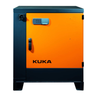
Fig. 8-3: Energy supply interface
1 Power connection X00
2 Air connection
3. Pull the cable from the smartPAD through the cable guide and
connect it to the robot controller at interface X19.
ready2_educate
90/154 | www.kuka.com BA ready2_educate V8 | Issued: 05.09.2018
Start-up and recommissioning