The use conditions are:
1) Speed is less than 2 km/h;
2) Not connected to fault diagnostic instrument;
3) Wire L (pin 7 in the internal diagnosis interface) is always grounded during diagnosis.
Besides, restore ECU mode of ABS to normal mode (diagnosis mode before) after DTC read.
Method: after diagnosis, disconnect wire L from ground, turn the key to off-power condition, and
connect again.
(2) Method of DTC read without fault diagnostic instrument
Read in the following steps if meeting the conditions of DTC read without fault diagnostic
instrument. The procedures in Fig. 3-16 are:
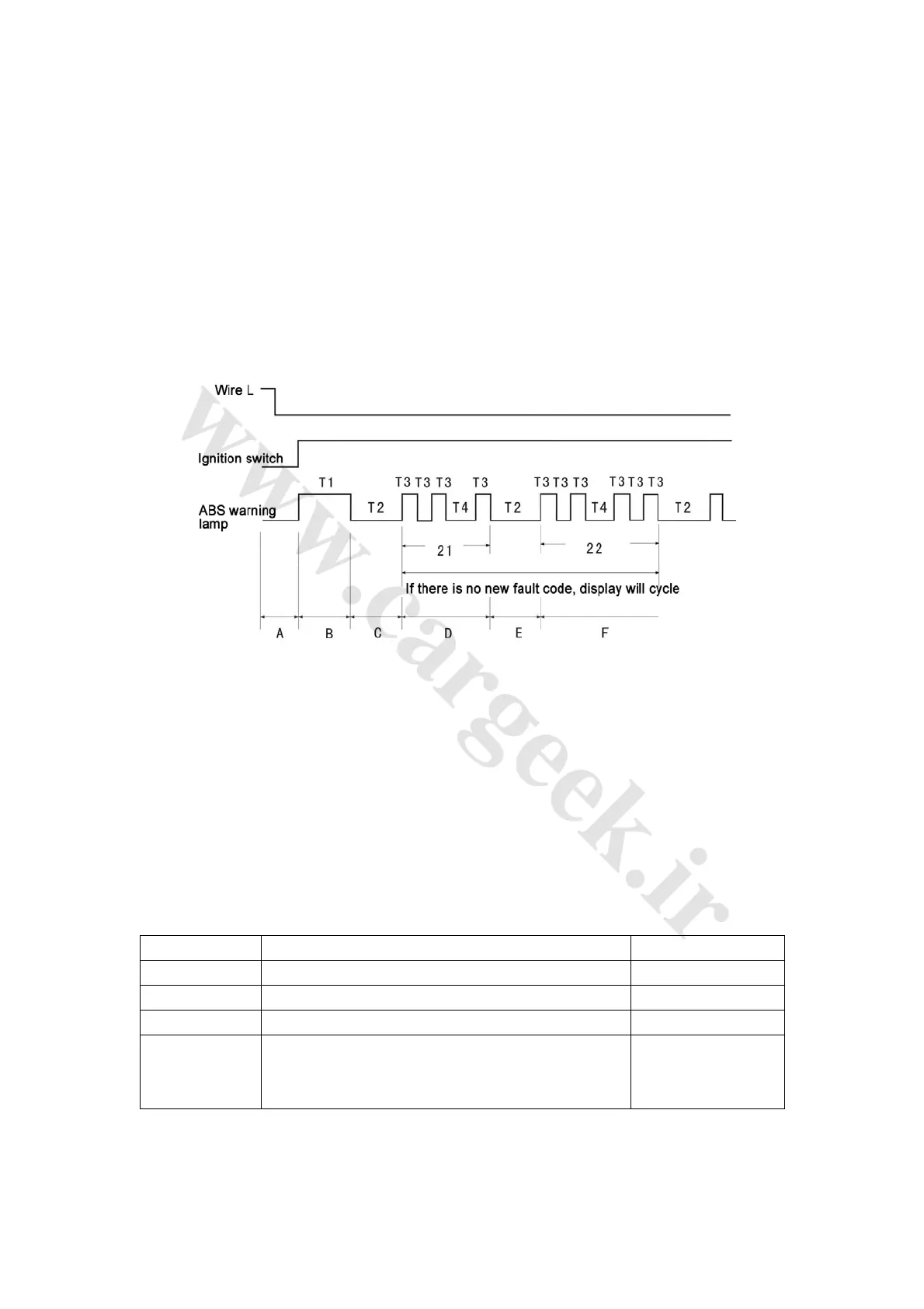
Fig. 3-16
1) Ground wire L and turn the vehicle key to connect the circuit;
2) ABS warning lamp is turned on and then turned off after 3 seconds, which indicates the start of
diagnosis;
3) ABS warning lamp is turned off for 3 seconds, which indicates the DTC display stage;
4) DTC read;
5) ABS warning lamp is turned off for 3 seconds, which indicates the next DTC display or circular
display stage;
6) New DTC display and read, or circular display of previous DTC.
The meaning of marks in Fig. 3-16 is listed in Table 3-7.
Table 3-7
Symbol Symbol description Duration
T1 Symbol of diagnosis start; warning lamp flickers 3.0s
T2 Interval of different DTC 3.0s
T3 Warning lamp flash interval in case of DTC 0.5s
T4
Interval of different digital place of a DTC (the ten’s place
is displayed before the interval and the unit’s place is
after the interval)
1.5s
Take the procedure illustrated in Fig. 3-16 for example. In the display area of the first DTC, as
warning lamp blinks twice (each on and off is T3, 0.5 second) before T4 (1.5 seconds before
warning lamp is turned on), the first mark (ten’s place) of the 2 digital code is 2; as warning lamp