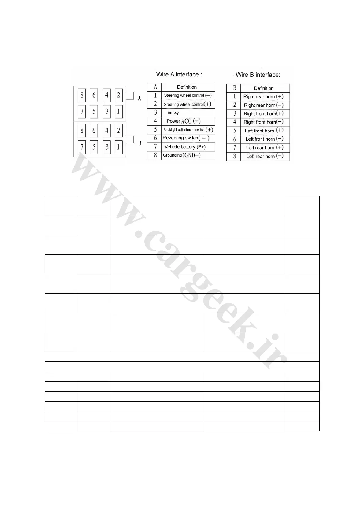
II. Definitions of Interfaces of Audio System
Fig. 4-105
Table 4-19
Testing
terminal
Wire
color
Terminal description Test condition
Standard
value
A1-body
W/G
Steering wheel control (-)
(reserved)
- -
A2-body
Y/W
Steering wheel control (+)
(reserved)
- -
A4-body
Y
Power input while ignition switch at
ACC
Ignition switch at ACC, always
10~14V
A5-body
R
Backlight signal input of audio
system
Combination switch at lamplet
position
10~14V
A6-body
G/N Reverse signal input Always
<1Ω
A7-body
W/Y
Normal power input of audio
system
Always
10~14V
A8-body
B Audio system grounding Always
<1Ω
B1-body
V Right rear speaker drive output (+) Audio system in process -
B2-body
V/B Right rear speaker drive output (-) Audio system in process -
B3-body
Gr Right front speaker drive output (+) Audio system in process -
B4-body
Gr/B Right front speaker drive output (-) Audio system in process -
B5-body
W Left front speaker drive output (+) Audio system in process -
B6-body
W/B Left front speaker drive output (-) Audio system in process -
B7-body
N Left rear speaker drive output (+) Audio system in process -
B8-body
N/B Left rear speaker drive output (-) Audio system in process -