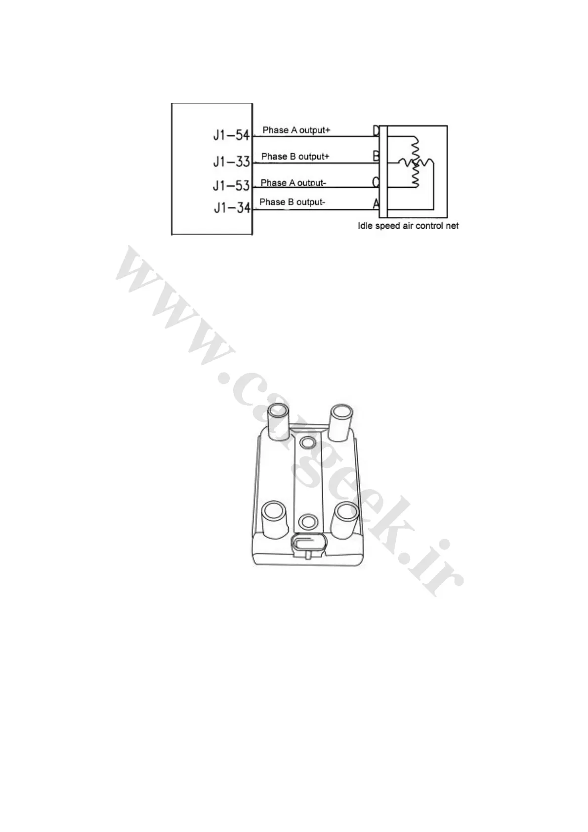
(3) Connection of wiring diagram (Fig. 1-16)
Fig. 1-16
(4) Trouble diagnosis: The short and open circuit of the two coils of the idle speed stepper motor
will be monitored by the ECU. When such troubles occur, the engine MIL will be lighted and the
engine will be operated under trouble mode. If the engine fails to work normally after check the
steps of the stepper motor with a diagnostic instrument, the intake air pressure should be checked
to ensure the normal operation of the piston of the stepper motor.
10. Ignition coil (Fig. 1-17)
Fig. 1-17
(1) Function: To convert primary winding low voltage electricity into secondary winding high
voltage electricity, to produce spark to burn the mixture of fuel and air in the cylinder.
(2) Separate ignition (grouped ignition): Based on the signal from the crankshaft/camshaft
position sensor, the ECU controls the grounding of the three ignition coils respectively for the
ignition of the engine.
(3) Structure and principle: Consists of primary winding, secondary winding, iron core, housing,
etc. When the battery is connected with the primary winding, the primary winding will be charged.
When the circuit of the primary winding is cut down by the ECU, the charge will stop. Meanwhile,
the high voltage electricity will be induced in the secondary winding.