II. Layout Diagram of Wiper and Washer System
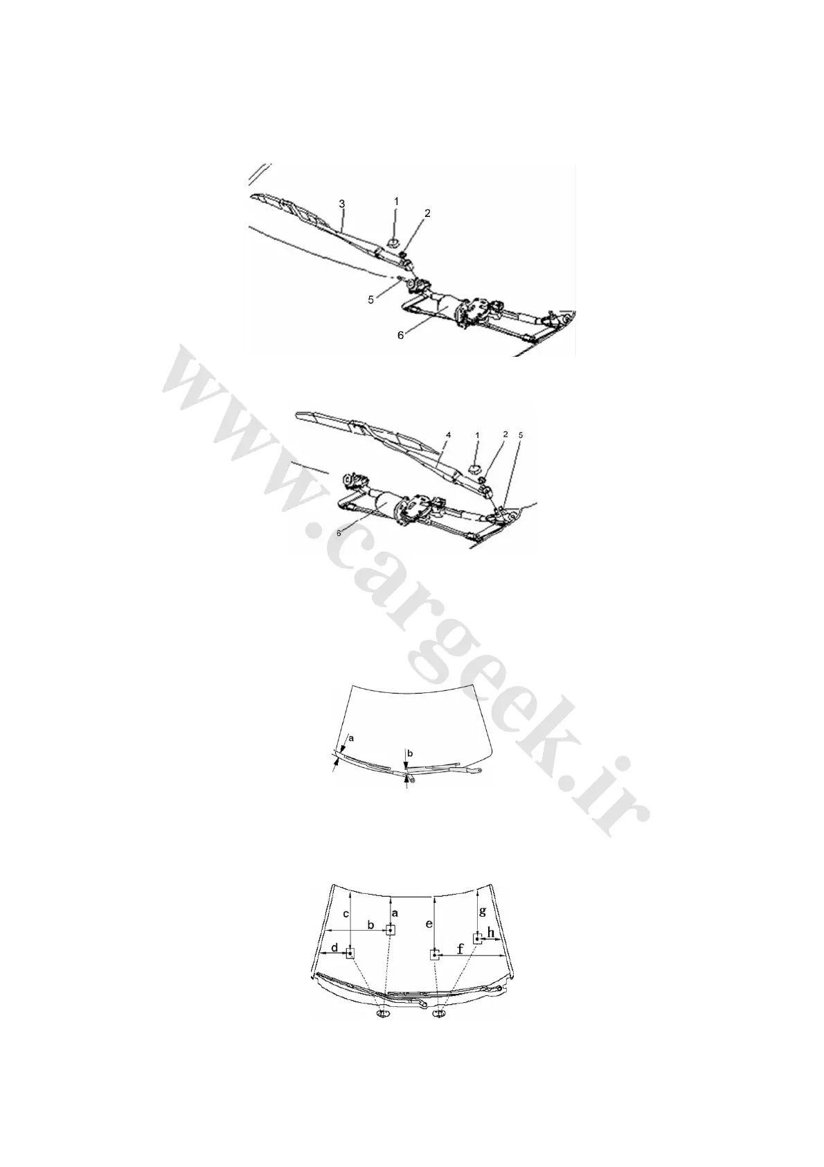
1. Layout diagram of wiper and washer system Fig. 4-91 and Fig. 4-92
Fig. 4-91
Fig. 4-92
1. Rocker arm cap pattern 2. Hexagon nut with taper spring gasket
3. Right rocker arm with blade 4. Left rocker arm with blade
5. Installing bolt of wiper motor and bracket assembly 6. Wiper motor and bracket assembly
2. Layout of main wiper blade Fig. 4-93
Fig. 4-93
Blade stop position: a=50-70mm b=40-60mm
Blade wiping angle: right blade =92°±3° left blade =82°±3°
3. Layout of washer nozzle Fig. 4-94 and Fig. 4-95
Fig. 4-94