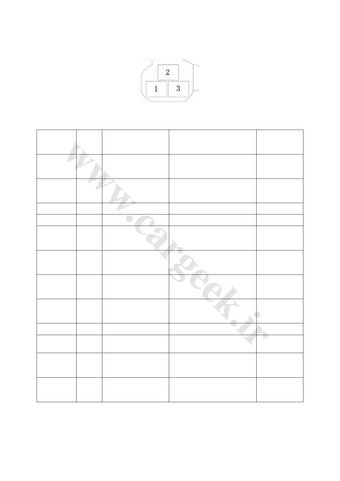
4. Switch of left front glass frame riser (Fig. 4-36 and Table 4-6)
Fig. 4-36
Table 4-6
Testing
terminal
Wire
color
Terminal description Test condition Standard value
1—body P/B
Left rear door glass frame
riser motor up
Ignition ON-position, rise-stop glass
4~5V →Less
than 1V
2—body P
Left rear door glass frame
riser motor down
Ignition ON-position, descend-stop
glass
4~5V →Less
than 1V
3—body G Safety switch Press safety switch, always
10~14V
6—body W/R Live power input B+ Always
10~14V
7—body N/B
Left front door glass frame
riser motor up
Ignition ON-position, rise-stop glass
4~5V →Less
than 1V
8—body N
Left front door glass frame
riser motor down
Ignition ON-position, descend-stop
glass
4~5V →Less
than 1V
9—body Y/B
Right rear door glass
frame riser motor up
Ignition ON-position, rise-stop glass
4~5V →Less
than 1V
10—body Y
Right rear door glass
frame riser motor down
Ignition ON-position, descend-stop
glass
4~5V →Less
than 1V
12—body B Electrical ground Always Less than 1Ω
14—body R Backlight power Lamplet on, backlight dim-bright
Pulse signal
generated
15—body U/G
Right front glass frame
riser motor up
Ignition ON-position, rise-stop glass
4~5V →Less
than 1V
16—body U/Y
Right front glass frame
riser motor down
Ignition ON-position, descend-stop
glass
4~5V →Less
than 1V