Section IV Fuel System
I. Removal and Installation
1. Operation before removal
① Suck the fuel
Avoid fuel flowing to the floor ②
Remove the secondary muffler ③
2. Operation after installation
Fill fuel ①
Co② nfirm if there is fuel leakage
Install③ the secondary muffler
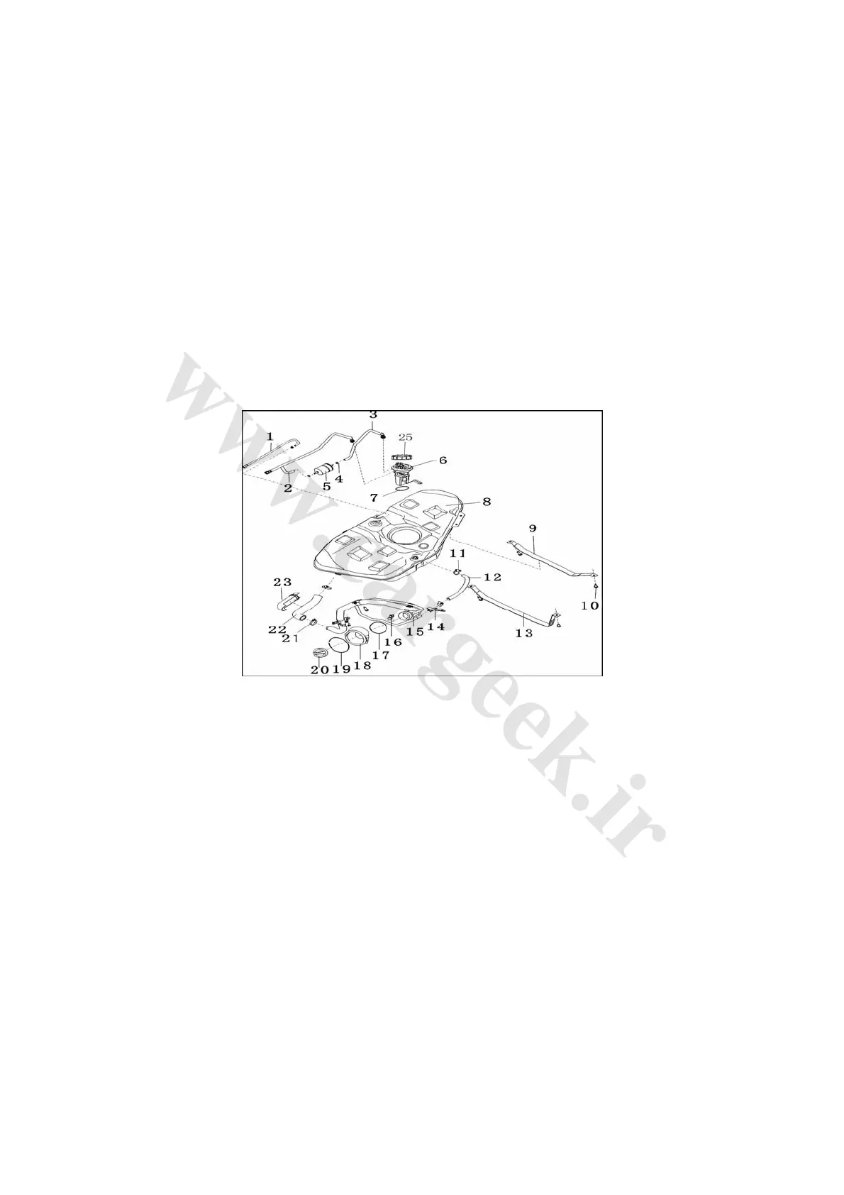
3 .Removal procedures as shown in Fig. 2-79
Fig. 2-79
1. Components of hose connecting fuel tank and canister 2. Components of fuel tank return pipe
3. Components of fuel tank/filter hose 4. Steel band type flexible ring clamps
5. Fuel filter 6. Fuel pump assembly
7. Oil pump seal 8. Fuel tank assembly
9. Components of right fixing strap of fuel tank 10. Hex bolt with flat washer (40N·m)
11. B-type worm-driven hoop 12. Oil return hose
13. Components of left fixing strap of fuel tank 14. Air return tube mount B
15. Upper components of filler tube 16. Air return tube mount A
17. Snap spring under the oil filler shield 18. Oil filler shield
19. Snap spring above the oil filler shield 20. Components of oil filler cap
21. B-type worm-driven hoop 22. Lower section of filler tube
23. Filler tube lower shield
4. Notes for fuel tank removal
(1) Raise the vehicle by a lifter. Assistant support should be provided when supporting/raising the
fuel tank by a jack to avoid the fuel tank turning over.
(2) Do not attempt to repair a certain section of the rubber tube, but replace the entire tube
instead.