3. Tachometer fault
(1) Check steps
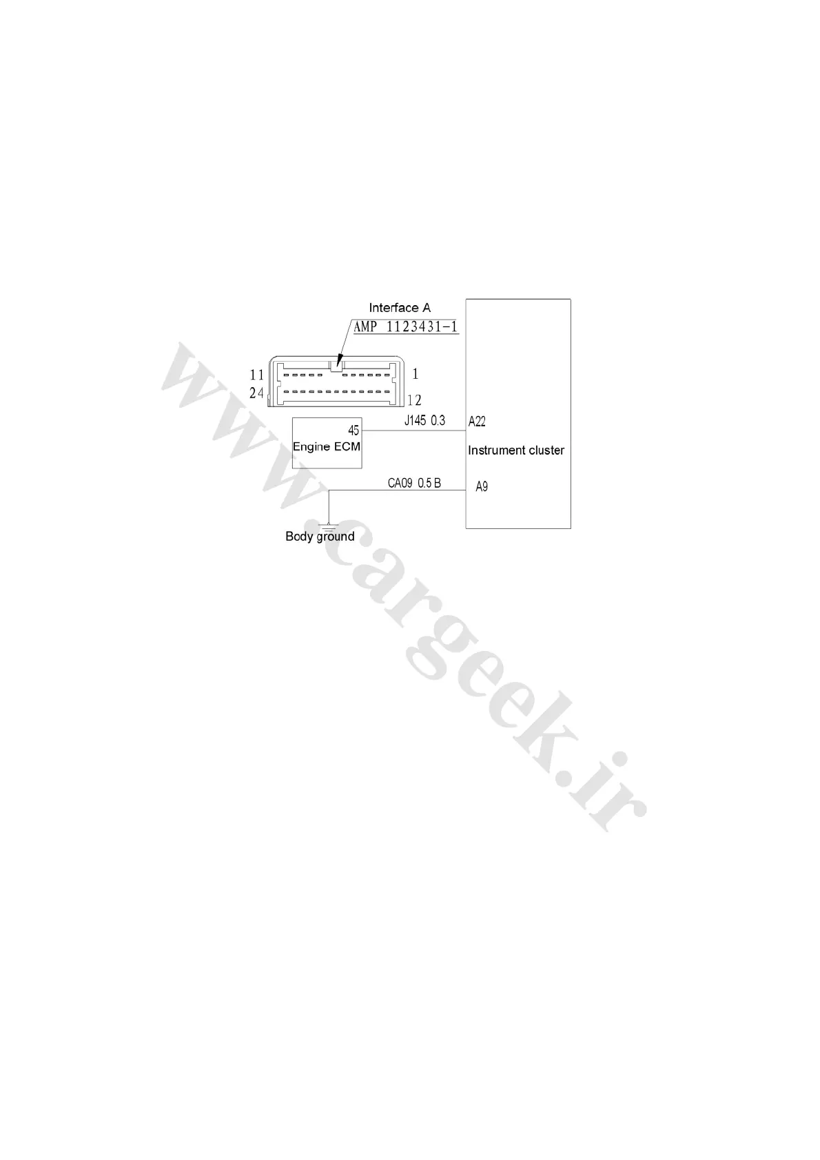
1) Check rotation speed signal output of engine ECM.
Check the voltage between connector terminals A22 and A9 of instrument cluster when engine
runs, normally, pulsed voltage peaking around 5V generated.
If it is in a normal condition, replace the instrument cluster, if not, repair or change the wire,
connector or electronic injection system.
2) Check the circuit as shown in Fig. 4-22.
Fig. 4-22
4. Fuel gauge fault
(1) Check steps
1) Check the resistance of fuel level sensor.
Disconnect fuel pump harness connector F11, check the resistance between connector terminals
2-F11 and 3-F11 of fuel level sensor when the floater of fuel level sensor is between E and F.
Resistance corresponding to floater position F is around 1~5Ω, while resistance corresponding to
floater position E is around 112~116Ω.
If it is in a normal condition, go to step 2), if not, change the fuel level sensor (located on fuel
pump).
2) Check the wiring and connector between instrument cluster and fuel pump.
Dis① connect the instrument cluster harness connector, fuel pump harness connector F11
remains disconnected.
Measure the ② impedance between A23 and 3-F11, normally less than 1Ω.
Measure the impedance between ③ harness terminal A9 and the body, normally less than 1Ω.
Measure the impedance between ④ instrument cluster terminal A23 and the body, normally more
than 100KΩ.
⑤ Measure the impedance between instrument cluster terminal A9 and the body, normally more
than 100KΩ.
If it is in a normal condition, replace the instrument cluster, if not, repair or change the wire and
connector.