If it is in a normal condition, go to step 2), if not, repair or change the fuse, wire and connector.
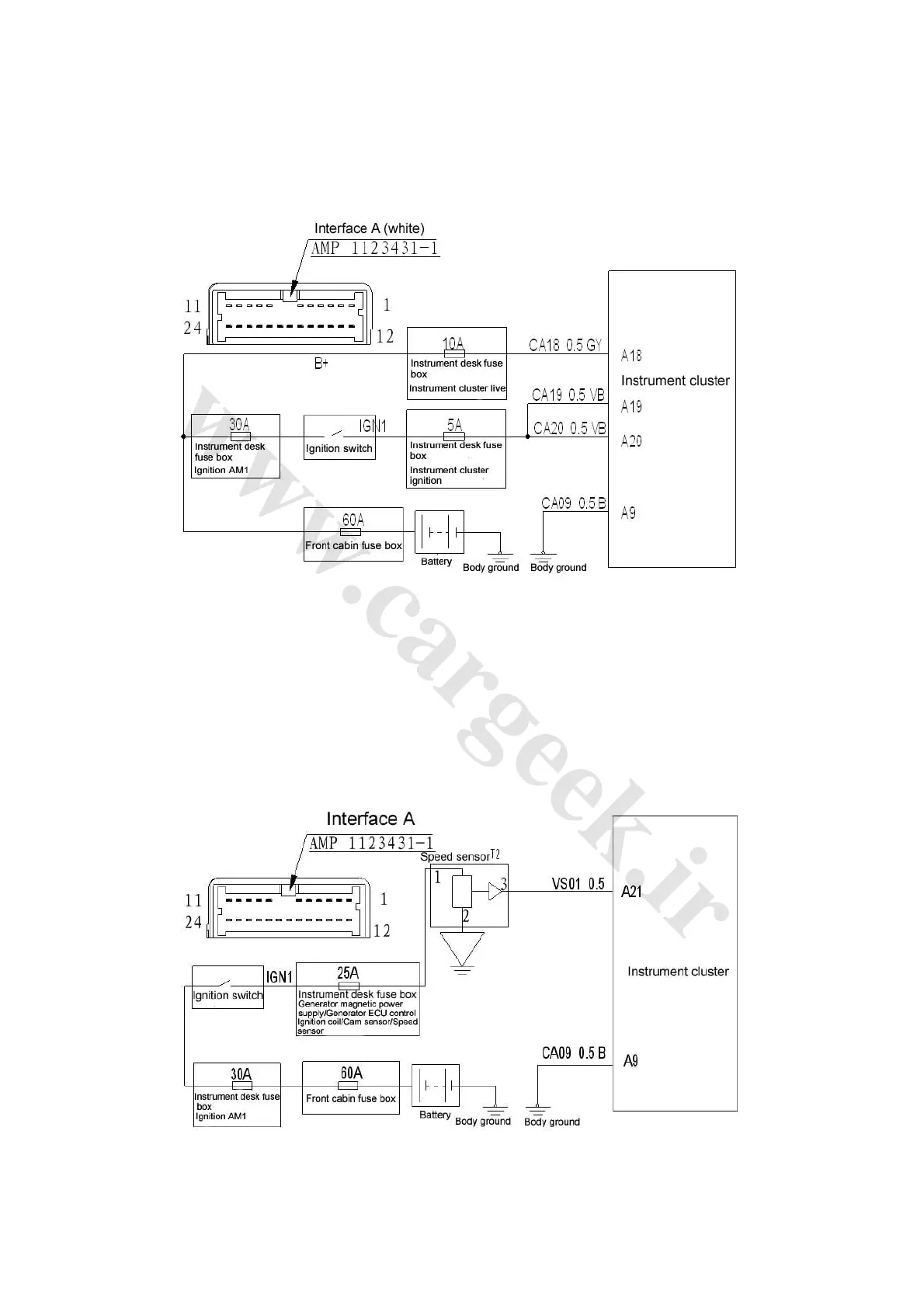
2) Check the ground end of speed sensor as shown in Fig. 4-20.
Check the resistance between 2-T2 and the body, normally less than 1Ω. If it is in a normal
condition, go to step 3), if not, repair or change the wire and connector.
Fig. 4-20
3) Check the instrument cluster.
Shift lever N-position, lift front wheels with lifter, ignition switch ON-position, check the voltage
between harness terminals A21 and A9 of instrument cluster when wheels turn slowly, normally,
pulsed voltage peaking around 5~14V generated.
If it is in a normal condition, replace the instrument cluster, if not, repair or change the wire and
connector as well as the speed sensor.
(2) Check the circuit as shown in Fig. 4-21.
Fig. 4-21