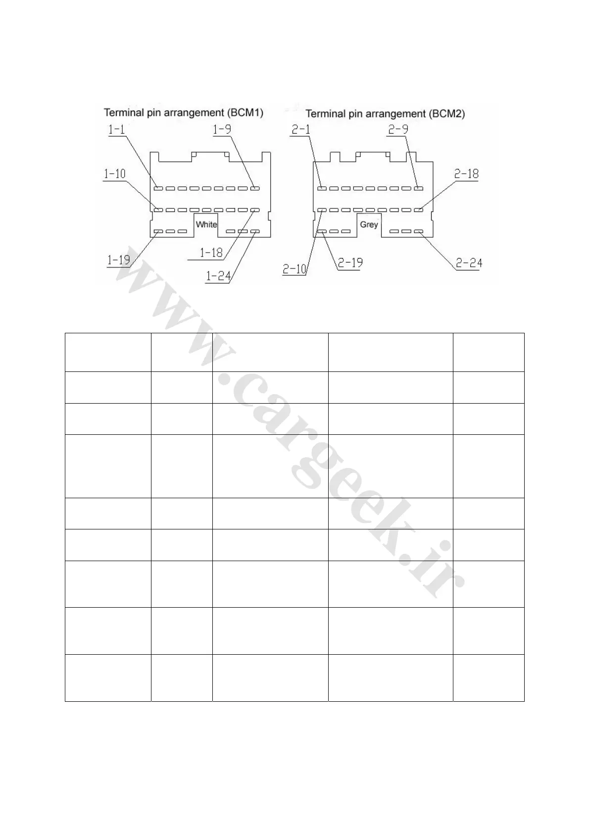
II. Reverse radar system terminal: See Fig. 4-111 and Table 4-22.
Fig. 4-111
Table 4-22
Testing terminal Wire color Terminal description Test condition
Standard
value
BCM (1-8) - body G/N Input reverse signal
Turn ignition switch to ON,
take reverse gear, always
10~14V
10~14V
BCM (1-19) - body W/B
Input reverse LIN signal to
instrument
Data transmission
Pulse signal
generated
BCM (2-18) - body R/Y
Output BCM fault warning
to instrument cluster
indicator
When reverse radar warns
barriers
10~14V
BCM (2-20) - body B
Ultrasonic probe power
negative
Always Less than 1Ω
BCM (2-21) - body G
Ultrasonic probe power
positive
Always 10~14V
BCM (2-22) - body Y
Ultrasonic probe 1 signal
wire
When probe works after
BCM sends out starting
signal
Pulse signal
generated
BCM (2-23) - body R/W
Ultrasonic probe 2 signal
wire
When probe works after
BCM sends out starting
signal
Pulse signal
generated
BCM (2-24) - body Y/R
Ultrasonic probe 3 signal
wire
When probe works after
BCM sends out starting
signal
Pulse signal
generated