(1) Function: To provide the information that whether oxygen in the cylinder is too high after the
fuel is burned with the air in the cylinder. With this information, the ECU can carry out closed loop
control for the fuel ration. Therefore, the three main toxic elements (HC, CO, and NOX) of the
engine exhaust can be best converted and purified in the three-way catalytic converter.
(2) Structure and principle: The sense element of the oxygen sensor is a ceramic pipe with holes
and gaps. The pipe is surrounded by engine exhaust and the air flows within the pipe. The ceramic
pipe wall is a kind of solid electrolyte with electric heating tube inside, which begins work when the
ceramic pipe has been heated to 300℃ (a feature of a solid electrolyte). With such a special
material, the oxygen ions can freely go through the ceramic pipe. Then, the concentration
difference of the mixture will be converted into potential difference, which will be put out in the form
of electric signal. If the concentration of the mixture is relatively high, the concentration difference
of the oxygen ions inside and outside the ceramic pipe will be relatively high, and the potential
difference will be relatively high as well. At the same time, a lot of oxygen ions will move to the
outside from the inside, and the voltage output will be relatively high. If the concentration of the
mixture is relatively low, the concentration difference of the oxygen ions inside and outside the
ceramic pipe will be relatively low, and the potential difference will be relatively low as well. At the
same time, little oxygen ions will move to the outside from the inside, and the voltage output will be
relatively low. The working voltage of the oxygen sensor fluctuates from 0.1V to 0.9V, which will be
changed for 5-8 times within 10 seconds. In case of lower than the changing frequency, the
oxygen sensor shall be renewed, as it can not be repaired.
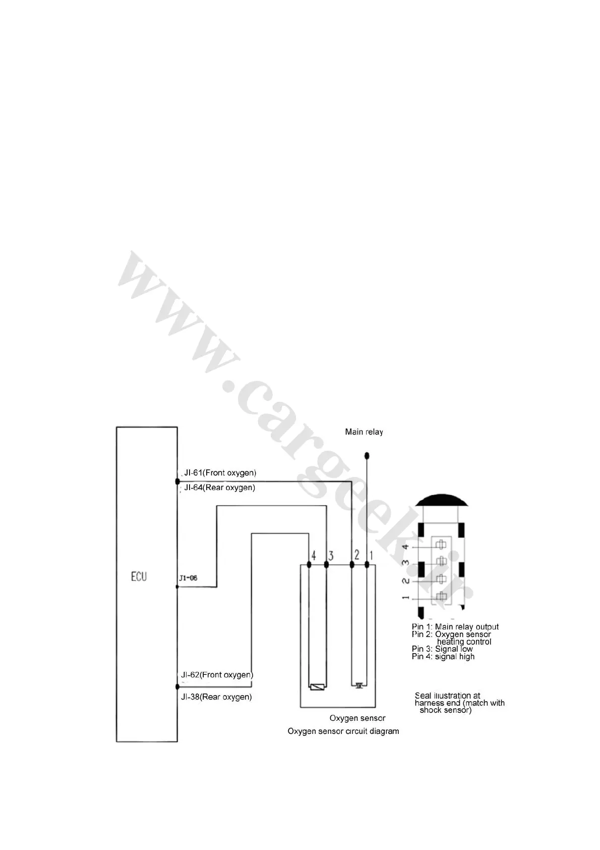
(3) Connection of wiring diagram: See oxygen sensor circuit diagram (Fig. 1-9)
Fig. 1-9