Gocator Line Profile Sensors: User Manual
Gocator Web Interface • 103
Scan Setup and Alignment
The following sections describe the steps to configure Gocator sensors for laser profiling using the Scan
page. Setup and alignment should be performed before adding and configuring measurements or
outputs.
Scan Page Overview
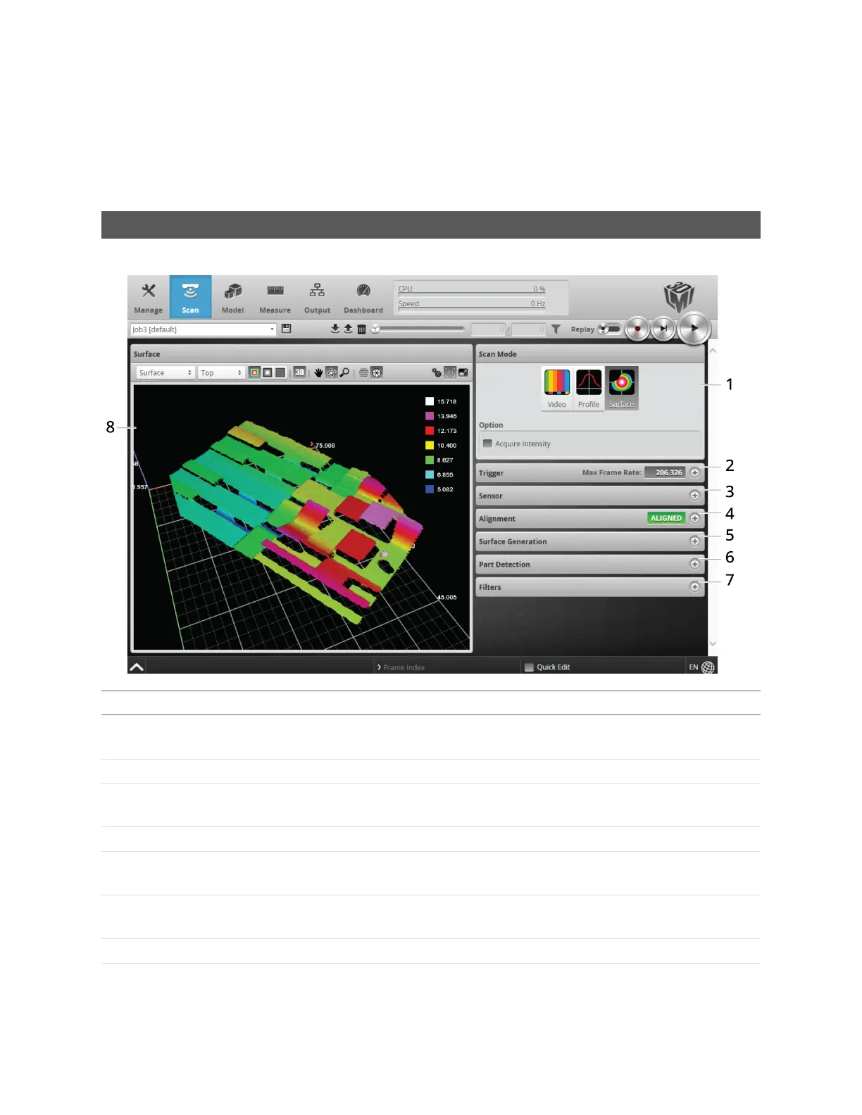
The Scan page lets you configure sensors and perform alignment.
Element Description
1 Scan Mode panel
Contains settings for the current scan mode and other options. See Scan Modes on the
next page.
2 Trigger panel
Contains trigger source and trigger-related settings. See Triggers on page 105.
3 Sensor panel
Contains settings for an individual sensor, such as active area or exposure. See Sensor on
page 112.
4 Alignment panel
Used to perform alignment. See Alignment on page 125.
5 Surface Generation
panel
Contains settings for surface generation. See Surface Generation on page 134.
6 Part Detection
panel
Used to set the part detection logic for sorting data into discrete objects. See Part
Detection on page 137.
7 Filters panel
Contains settings for post-processing of the profiles. See Filters on page 130.
8 Data Viewer Displays sensor data and adjusts regions of interest. Depending on the current operation
mode, the data viewer can display video images or scan data. See Data Viewer on page
144.