Gocator Line Profile Sensors: User Manual
Specifications • 621
Function Pins
Max Collector
Current
Max Collector–Emitter
Voltage
Min Pulse Width
Out_1 N, O 40 mA 70 V 20 µs
Out_2 S, T 40 mA 70 V 20 µs
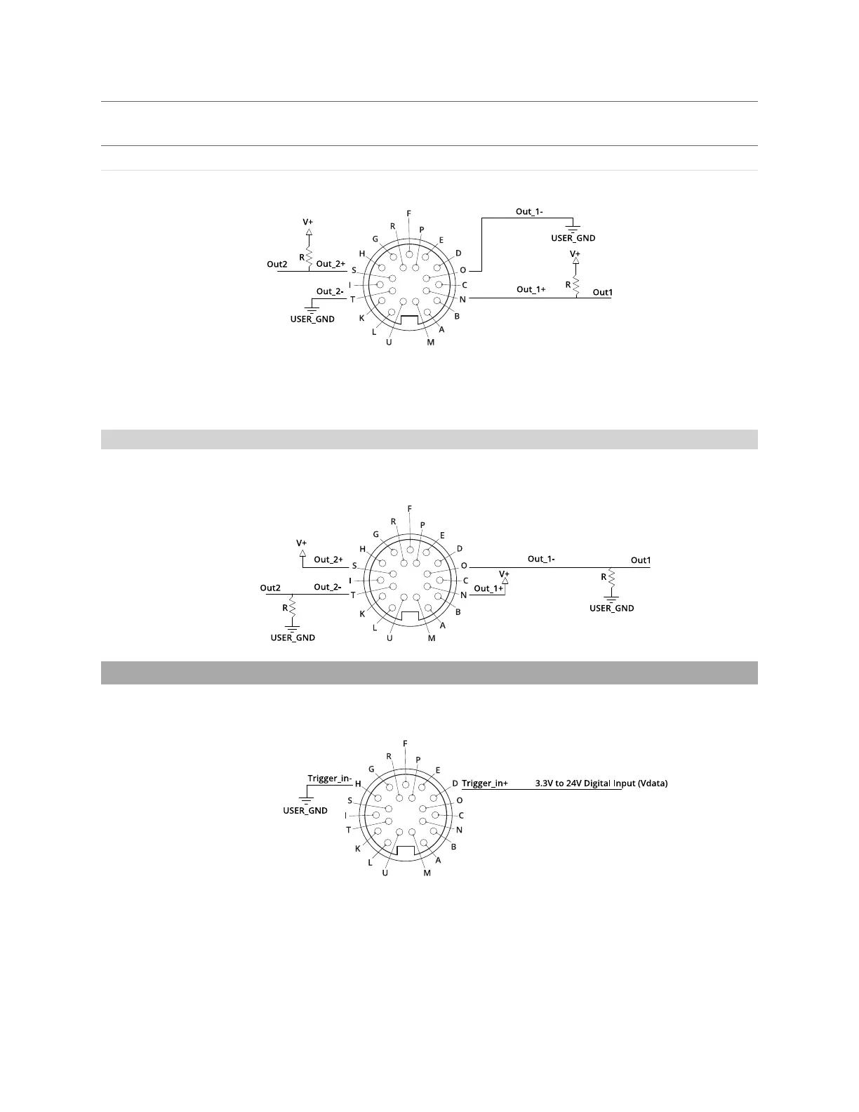
The resistors shown above are calculated by R = (V+) / 2.5 mA.
The size of the resistors is determined by power = (V+)^2 / R.
Inverting Outputs
To invert an output, connect a resistor between ground and Out_1- or Out_2- and connect Out_1+ or
Out_2+ to the supply voltage. Take the output at Out_1- or Out_2-. For resistor selection, see above.
Digital Input
Every Gocator sensor has a single optically isolated input. To use this input without an external resistor,
supply 3.3 - 24 V to the positive pin and GND to the negative.
Active High
If the supplied voltage is greater than 24 V, connect an external resistor in series to the positive.The
resistor value should be R = [(Vin-1.2V)/10mA]-680.
 Loading...

