Gocator Line Profile Sensors: User Manual
How Gocator Works • 59
For more information, see the Profile Bounding Box tool or the Surface Bounding Box tool, and the
Script tool.
Spacing (Data Resampling)
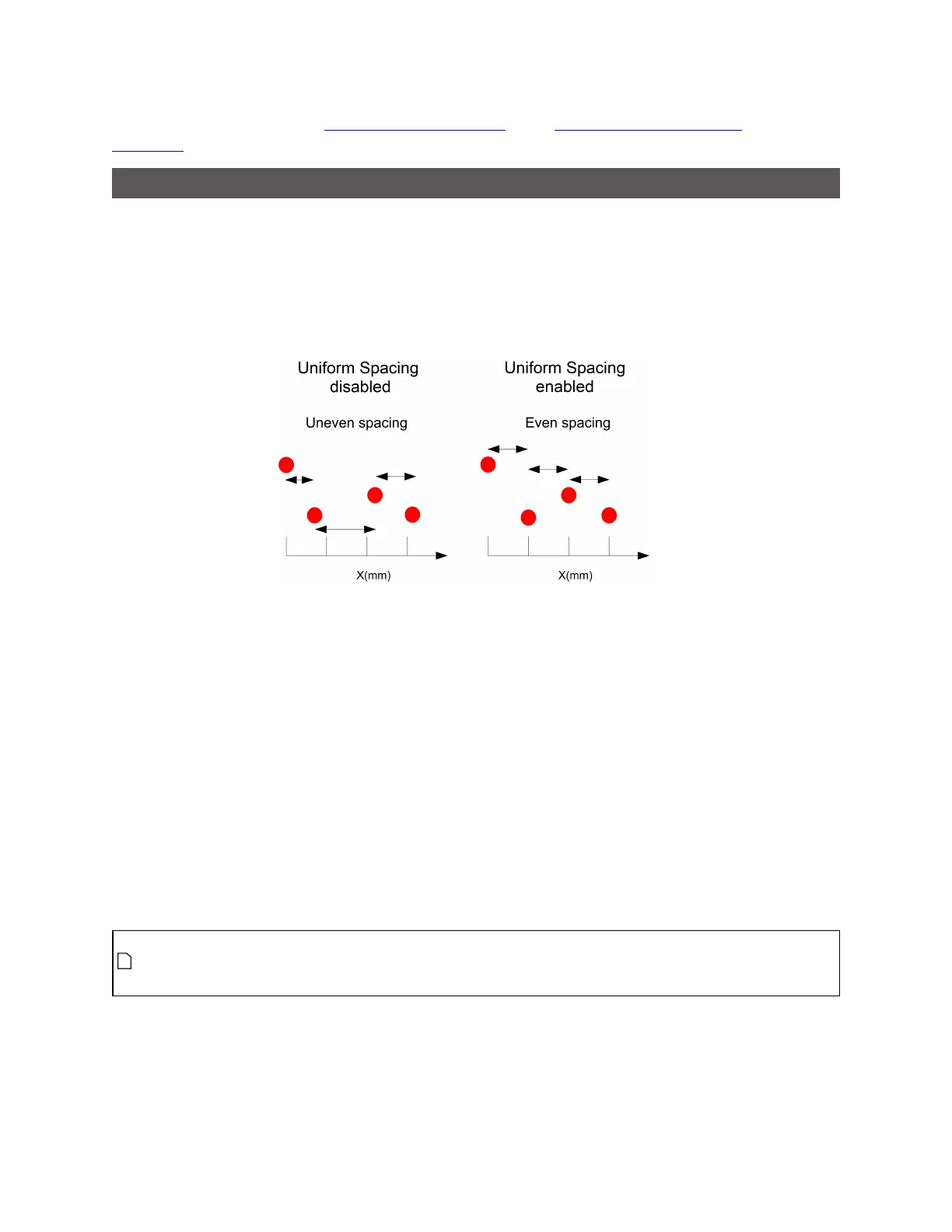
Data produced in Profile mode is available in two formats: with and without uniform spacing. Uniform
spacing is enabled in the Scan Mode panel, on the Scan page.
When uniform spacing is enabled, the ranges that make up a profile are resampled so that the spacing is
uniform along the laser line (X axis). The resampling divides the X axis into fixed size "bins." Profile points
that fall into the same bin are combined into a single range value (Z). The size of the spacing interval is
set under the Spacing tab in the Sensor panel on Scan page.
Resampling to uniform spacing reduces the complexity for downstream algorithms to process the profile
data from the Gocator, but places a higher processing load on the sensor's CPU.
When uniform spacing is not enabled, no processing is required on the sensor. This frees up processing
resources in the Gocator, but usually requires more complicated processing on the client side. Ranges in
this case are reported in (X, Z) coordinate pairs.
Most built-in measurement tools in the Gocator in Profile mode operate on profiles with uniform
spacing. Alimited number of tools can operate on profiles without uniform spacing. For more
information on the profile tools, see Profile Measurement on page 202.
A drawback of uniform spacing is that if sensors are angled to scan the sides of a target, data on the
"verticals"is lost because points falling in the same "bin"are combined. When Uniform Spacing is
disabled, however, all points are preserved on the sides. In this case, the data can be processed by the
subset of tools that work on profiles without uniform spacing. Alternatively, the data can be processed
externally using the SDK.
When uniform spacing is enabled, in the Ethernet output, only the range values (Z) are reported
and the X positions can be reconstructed through the array index at the receiving end (the
client). For more information on Ethernet output, see Ethernet Output on page 319.
For information on enabling uniform spacing, see Scan Modes on page 104.