Gocator Line Profile Sensors: User Manual
Gocator Web Interface • 243
See Scripts on page 313 for more information on the script syntax.
To create or edit a Script measurement:
1. Add a new Script tool or select an existing Script measurement.
2. Edit the script code.
3. Add script outputs using the Add button.
For each script output that is added, an index will be added to the Output drop-down and a unique ID
will be generated.
To remove a script output, click on the button next to it.
4. Click the Save button to save the script code.
If there is a mistake in the script syntax, the result will be shown as a "Invalid" with a red border in the
data viewer when you run the sensor.
Outputs from multiple measurement tools can be used as inputs to the script. A typical script would
take results from other measurement tools using the value and decision function, and output the result
using the output function. Stamp information, such as time and encoder stamps, are available in the
script, whereas the actual profile3D point cloud data is not. (The script engine is not powerful enough to
process the data itself.) Only one script can be created.
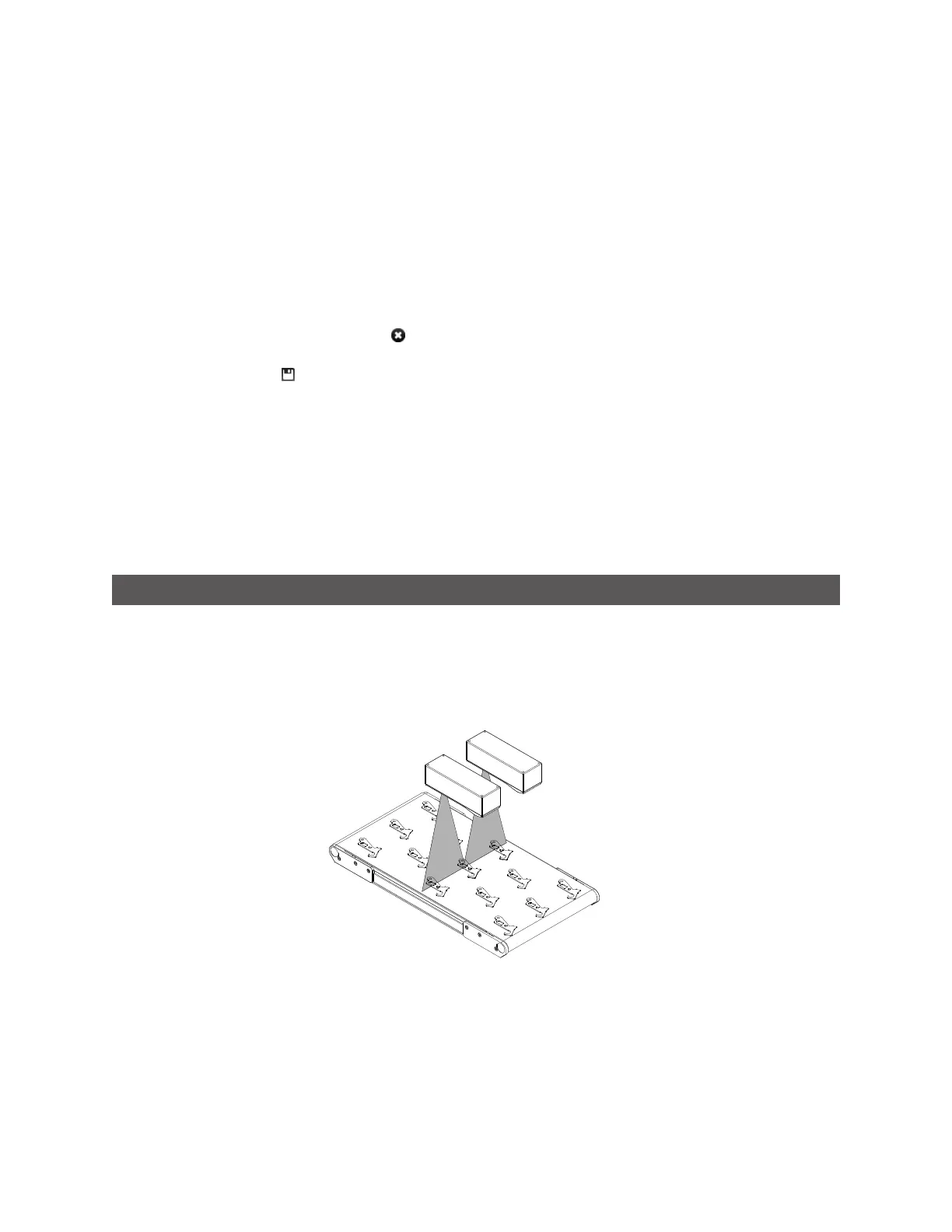
Surface Measurement
Surface measurement involves capturing a sequence of laser profiles, optionally identifying discrete
objects, and measuring properties of the surface or the objects, such as the volume of the object or the
height at a certain position of the object. All volumetric tools have the ability to operate either on the
entire surface or the full object, or within a region of interest at a certain position in relation to the
surface or an object.
Multiple measurements can be performed on the entire surface or each discrete object, limited only by
the available CPU resources.
The frame of reference for the coordinate system of the detected object can be set to Sensor or Part in
the Part Detection panel (Part Detection on page 137). This setting determines what coordinate system