Gocator Line Profile Sensors: User Manual
Protocols • 505
Modbus Protocol
Modbus is designed to allow industrial equipment such as Programmable Logic Controllers (PLCs),
sensors, and physical input/output devices to communicate over an Ethernet network.
Modbus embeds a Modbus frame into a TCP frame in a simple manner. This is a connection-oriented
transaction, and every query expects a response.
This section describes the Modbus TCP commands and data formats. Modbus TCP communication lets
the client:
l Switch jobs.
l Align and run sensors.
l Receive measurement results, sensor states, and stamps.
To use the Modbus protocol, it must be enabled and configured in the active job.
The Gocator 4.x firmware uses mm, mm
2
, mm
3
, and degrees as standard units. In all protocols,
values are scaled by 1000, as values in the protocols are represented as integers. This results in
effective units of mm/1000, mm
2
/1000, mm
3
/1000, and deg/1000 in the protocols.
If buffering is enabled with the Modbus protocol, the PLC must read the Buffer Advance output register
(see State on page 508) to advance the queue before reading the measurement results.
For information on configuring the protocol using the Web interface, see Ethernet Output on page 319.
Concepts
A PLC sends a command to start each Gocator. The PLC then periodically queries each Gocator for its
latest measurement results. In Modbus terminology, the PLC is a Modbus Client. Each Gocator is a
Modbus Server which serves the results to the PLC.
The Modbus protocol uses TCP for connection and messaging. The PLC makes a TCP connection to the
Gocator on port 502. Control and data messages are communicated on this TCP connection. Up to eight
clients can be connected to the Gocator simultaneously. A connection closes after 10 minutes of
inactivity.
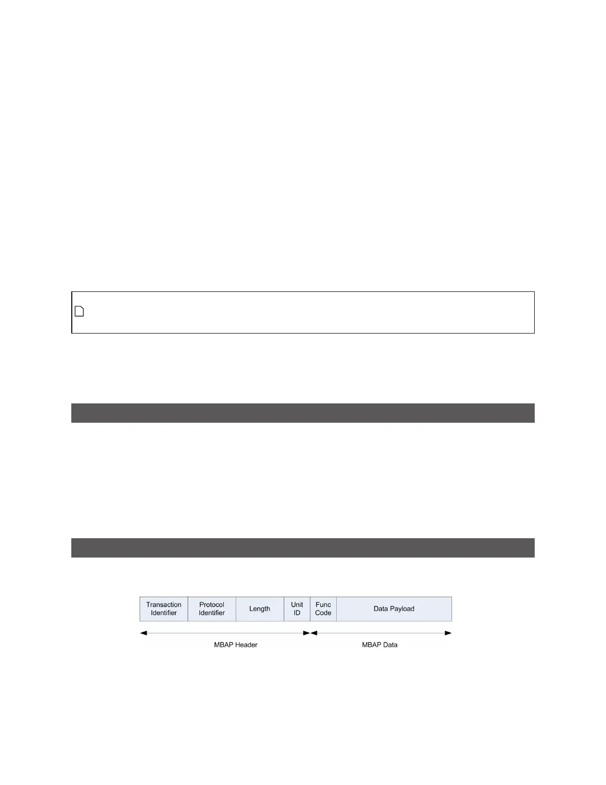
Messages
All Modbus TCP messages consist of an MBAP header (Modbus Application Protocol), a function code,
and a data payload.
The MBAP header contains the following fields: